Operating Instructions
2–14
1720/1721
0°
10°
d∅
10°
20%
dG
YL
10%
dG
yl
75% 100%
100%
75%
g
R
V
cy
MG
Q
b
U
B
mg
–I
CY
r
G
10°
20°
30°
40°
50°
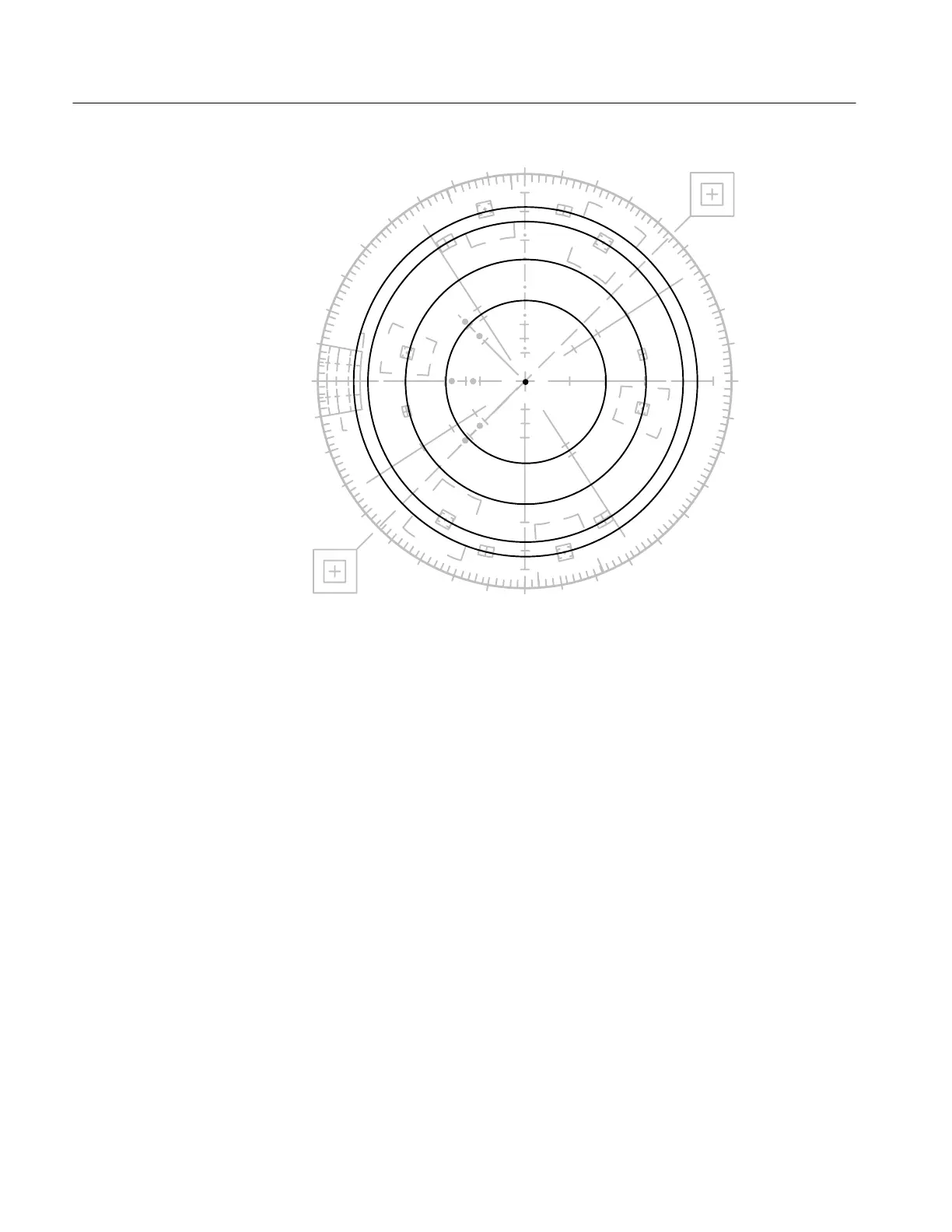
Figure 2-8: 1720/1721 test circle display.
6. Position Center Dot
Use a small screwdriver to adjust the vertical and horizontal positioning controls.
Check that there is sufficient range to move the dot through the geographic
center of the display (the graticule center target). It should be noted that the
amount of adjustment range varies from instrument to instrument.
Adjust the positioning controls to place the center dot at the exact center of the
graticule.
7. Set Gain
With the test circle displayed, use a screwdriver to adjust the GAIN CAL fully
clockwise and check that the outer circle is outside of the outer (Red and Cyan)
graticule targets.
Set the GAIN CAL fully counterclockwise and check that the outer circle is
inside of the outer (Red or Cyan) graticule targets.
Set the GAIN CAL so that the outer circle passes through the outer (Red and
Cyan) graticule targets.