Operating Instructions
2–12
1720/1721
4. Select Input
Select the Channel B input for a display of the modulated staircase signal. See
Figure 2-5.
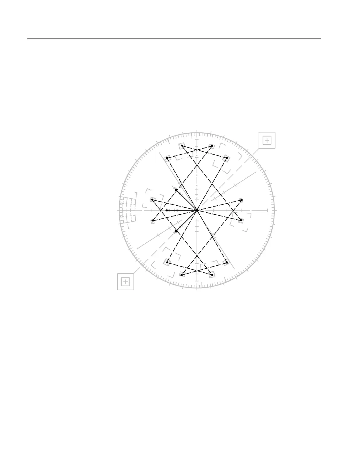
Push in and hold the INPUT button until both the CH-A and CH-B indicators are
lit, and check for a display of both vectors and modulated staircase. See Figure
2-6.
0°
10°
d∅
10°
20%
dG
YL
10%
dG
yl
75% 100%
100%
75%
g
R
V
cy
MG
Q
b
U
B
mg
–I
CY
r
G
10°
20°
30°
40°
50°
Figure 2-6: Color bar and modulated staircase signals both displayed on a 1721.
Briefly push the INPUT button and check that the CH-A indicator is the only
one lit and that only a vector display is present.
5. Select Reference
Connect the black burst signal to the EXT REF loop-through input and terminate
in 75Ω. See Figure NO TAG.