Maintenance
6–22
1720/1721
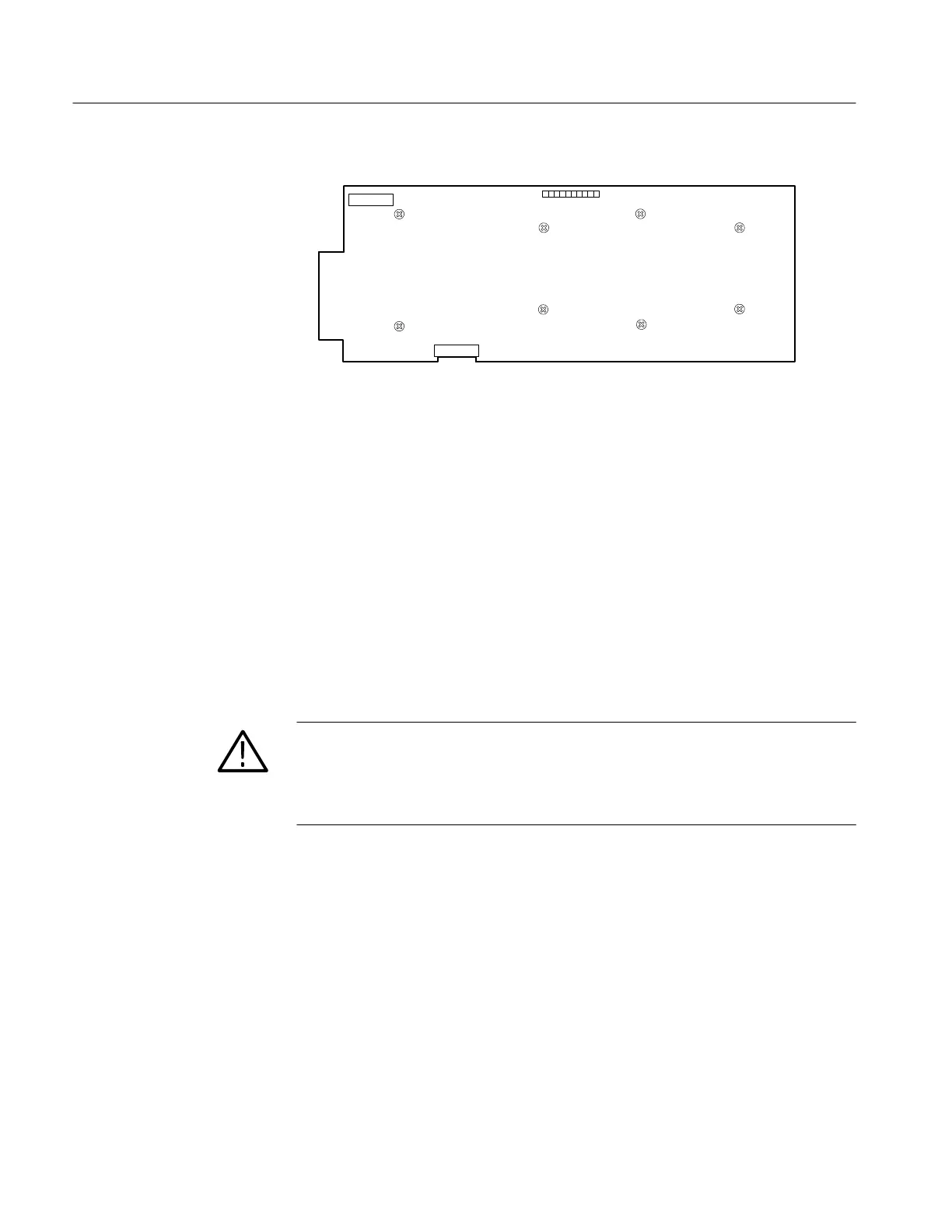
J216
J153
J933
A3 Main Bd
Front
Figure 6-6: Screws holding the main circuit board (A3) in place.
5. Remove the board by sliding it toward the rear panel until the toe of the
board clears the front, then lift out.
6. To replace the Main board, lay the board flat and slide it back into place.
7. To complete the replacement of the board, reverse the rest of the steps.
1. Remove the plug from J546 on the Power Supply board; it is the connection
to the Main board.
2. Remove the anode connection from the crt and discharge it to ground.
WARNING. CRT Retained Charge Hazard:
The crt may retain a dangerous charge. Ground the conductor of the anode to
discharge the crt. Do not allow the conductor to touch your body or any
circuitry.
3. Unsolder the following connections: J122 pins 1 through 4, J133 pins 1
through 4, and J215 the focus lead. (If a 1700F10 Field Upgrade Kit is
installed, unsolder leads to the rear-panel DC Connector.)
4. Disconnect the ac line filter from the rear panel by unscrewing its two
mounting screws.
5. Use a #1 Pozidrive tip to disconnect the power on/off switch from the front
casting.
6. Remove the seven screws that are holding the Power Supply board down.
See Figure 6-7.
7. Remove the board by sliding it forward and lifting it up.
Removing the Power
Supply Board