Installation
3–4
1720/1721
123
45
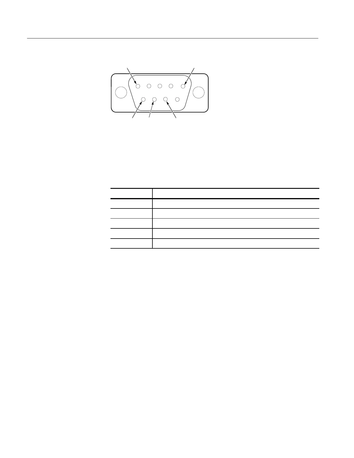
Ground
TXD RXD External
strobe out
67
89
Ground
Figure 3-3: View of the 1720/1721 rear panel showing AUXILIARY connector pins
with their functions.
Table 3–2: AUXILIARY Connector Pin Assignments
Pin # Use
2-3-4-6 No connection.
1-5 Ground.
7 External Strobe In for Line Select blanking.
8 RXD (Receive Data) 1730-Series communication to the 1720/1721.
9 TXD (Transmit Data) 1720/1721 return communication to 1730-Series.
Mechanical Installation
All qualification testing for the 1720/1721 was performed in a 1700F00 cabinet.
To guarantee compliance with specifications, the instrument should be operated
in a cabinet. The plain cabinet, 1700F00, is shown in Figure 3-4.
The portable cabinet, 1700F02, is shown in Figure 3-5. The 1700F02 has a
handle, four feet, a flip-up stand, and a front cover. This F02 cabinet is compat-
ible with the TEKTRONIX BP1 battery pack, which can be used as a dc power
source. The hole sizes and spacing are different from those of the 1700F00.
All of the 1700-Series metal cabinets, which are available from Tektronix as
Optional Accessories, provide the proper electrical environment for the
instrument. They supply adequate shielding, minimize handling damage, and
reduce dust accumulation within the instrument.
Cabinetizing