Installation
1720/1721
3–9
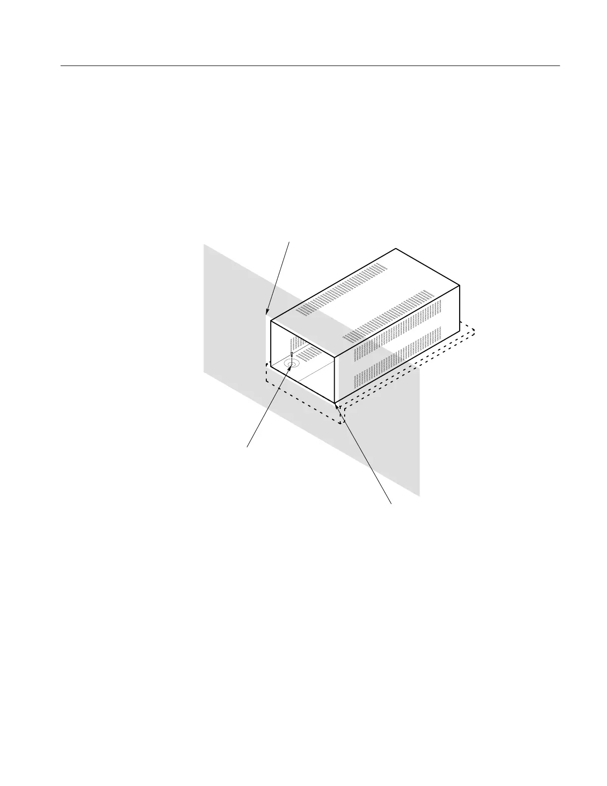
For applications such as consoles, the instrument can be mounted with front
molding flush or protruding from the console. In both cases, allow approximate-
ly 3 inches of rear clearance for BNC and power-cord connections.
To mount the 1720/1721 safely, attach it to a shelf strong enough to hold its
weight. Install the mounting screws through the four 0.156-inch diameter holes
in the bottom of the 1700F00 cabinet. See Figure 3-10.
Requires four 0.156”
holes below the 1700F00
cabinet to secure the
instrument to the shelf.
For Flush Front Panel: Cut hole the same size as
the monitor front molding to allow the monitor front
panel to align with the custom panel surface.
For Protruding Front Molding:
Cut hole in panel the same size
as the opening in the monitor
cabinet to allow the front panel
molding to cover the hole.
Figure 3-10: Typical custom installation showing the console.
Custom Installation

 Loading...


