Checks and Adjustments
1720/1721
5–21
g. Adjust R571 (Orthogonality) on the Main board for a straight vertical
line parallel to the Y axis.
h. Disconnect the Function Generator from the 1720/1721.
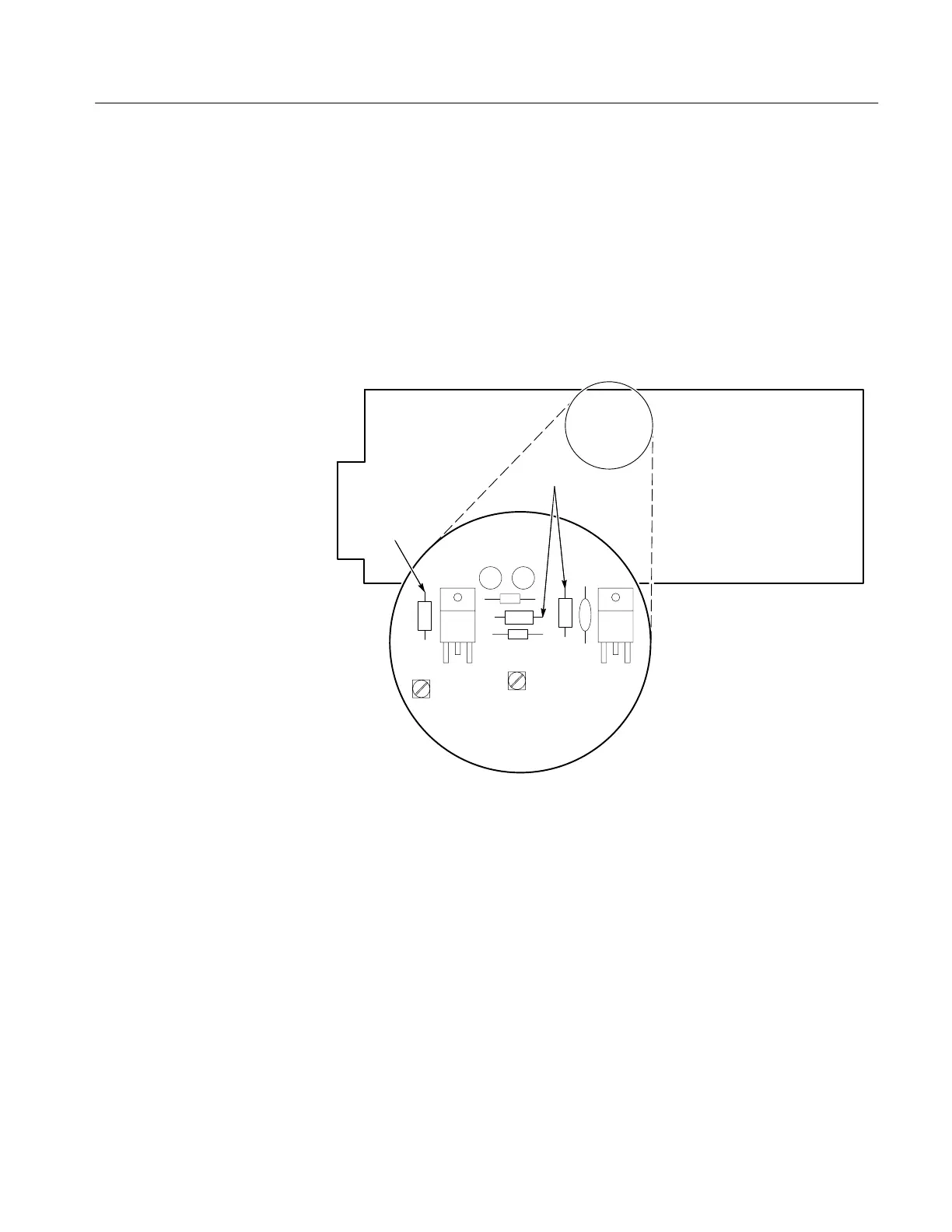
5. Adjust On–Board Regulated Power Supplies
a. Connect the voltmeter ground lead to one of the rear-panel ground lugs
and the active lead to the –11.8 V test point. See Figure 5-9.
A3 Main Bd
Front
R267
R259
–11.8 V
ADJUST
+11.8 V
ADJUST
–11.8 V
Test point
U172U164
+11.8 V
Test point
Figure 5-9: Test points and adjustment locations for the 11.8V supplies
b. Adjust R259 (–11.8 V ADJ) for –11.78 to –11.82 volts.
c. Connect the voltmeter active lead to the +11.8 V test point. See Figure
5-9.
d. Adjust R267 (+11.8 V ADJ) for +11.78 to +11.82 volts.
6. Adjust Lock-In Phase
a. Connect the Television Signal Generator output to the 1720/1721
Vectorscope as shown in Fig. 5-8.
b. Set the 1720/1721 INPUT to CH-B, MODE to VECTOR, and REF to
INT.