Introduction
1–6
1720/1721
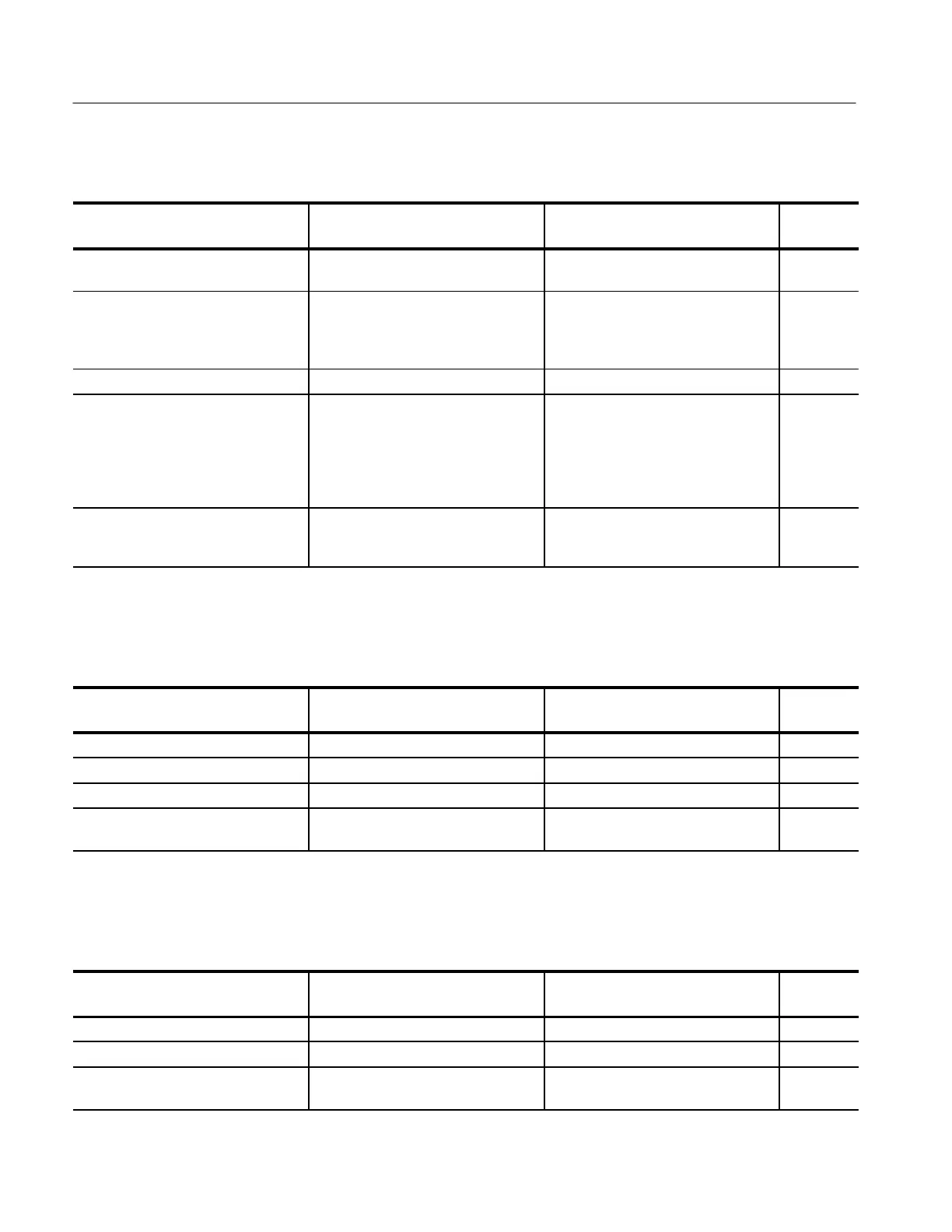
Table 1–3: XY Mode
Characteristic Performance requirement Supplemental information
Step
number
Input DC Coupled differential inputs through
rear-panel REMOTE connector.
Input amplitude 2 to 9 V
p–p
Adjustable full scale deflection 0 dBm
to +12 dBm for 600Ω system. Factory
set to 0 dBm. Specification verified
during calibration.
Maximum input voltage ±15 V peak signal plus DC.
Frequency response
High gain mode
DC to greater than 500 kHz.
DC to greater than 100 kHz.
3 dB point.
3 dB point. Not a differential input,
minus inputs must be grounded.
14
14
X and Y input phase matching Less than a trace width of separation
at 20 kHz.
Single ended. Phase matching may be
improved, above 20 kHz, by adjusting
C484.
13
Table 1–4: CRT Display
Characteristic Performance requirement Supplemental information
Step
number
CRT viewing area 80 X 100 mm.
Accelerating Potential 15.75 kV
Trace rotation range Greater than ±1° from horizontal. Total adjustment range is typically 8°. 12
Graticule Internal vector, variable scale illumina-
tion.
Table 1–5: Power source
Characteristic Performance requirement Supplemental information
Step
number
Mains voltage ranges 90 – 250 V. Continuous range from 90 to 250 VAC. 2
Mains frequency range 48 – 66 Hz.
Power consumption 0.7 A maximum, 0.35 A (21.4 Watts)
typical.