Checks and Adjustments
5–10
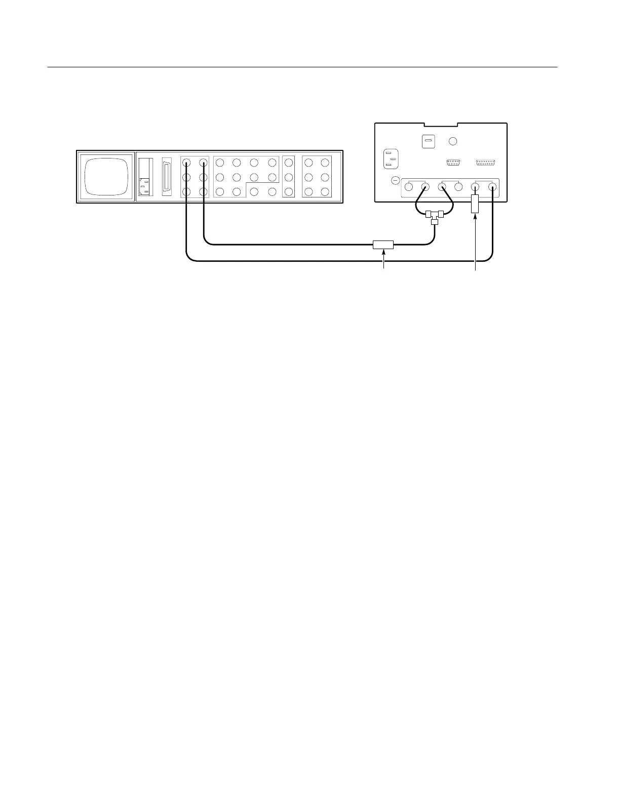
1720/1721
1720/1721 (rear)
Black burst
75W Termination
1410–Series (rear)
Color bar
75W
Feed–through
terminator
Figure 5-4: Signal connection for checking CH-A/CH-B phase matching.
b. CHECK – that the CH-A to CH-B phase match is within ±0.5°.
c. Remove the black burst signal from the EXT REF INPUT. Move the
connection from CH-A to the EXT REF. Alternately display INPUT B
with INT and EXT REF.
d. CHECK – that there is less than 0.5° burst jitter with either INT or EXT
REF.
e. Disconnect the color bar signal from the dual input coupler and apply the
linearity staircase signal, with 40 IRE subcarrier (280 mV PAL and
PAL-M). Display the signal in VECT MODE. Set the Staircase vector
dot to the left horizontal graticule line with the PHASE control.
f. Rotate the VARIABLE control until the staircase vector is one-third
longer (+3 dB) and to the point that the vector has been decreased to
one-half of the original vector length (–6 dB).
g. CHECK – that there is less than 1° phase change over this range.
8. Check Amplifier Linearity
REQUIREMENT – Differential Phase: v 1°, Differential Gain: v 1%,
(Measured with a 140 IRE (1 V PAL) linearity signal (5–step, 10–step, or
ramp) with a 40 IRE (300 mV PAL) subcarrier.
a. Display the modulated staircase in VECT MODE. With the PHASE
control, position the vector dot (representing the subcarrier on the