Installation
1720/1721
3–3
1
234
5
678
91011
12
13
14
15
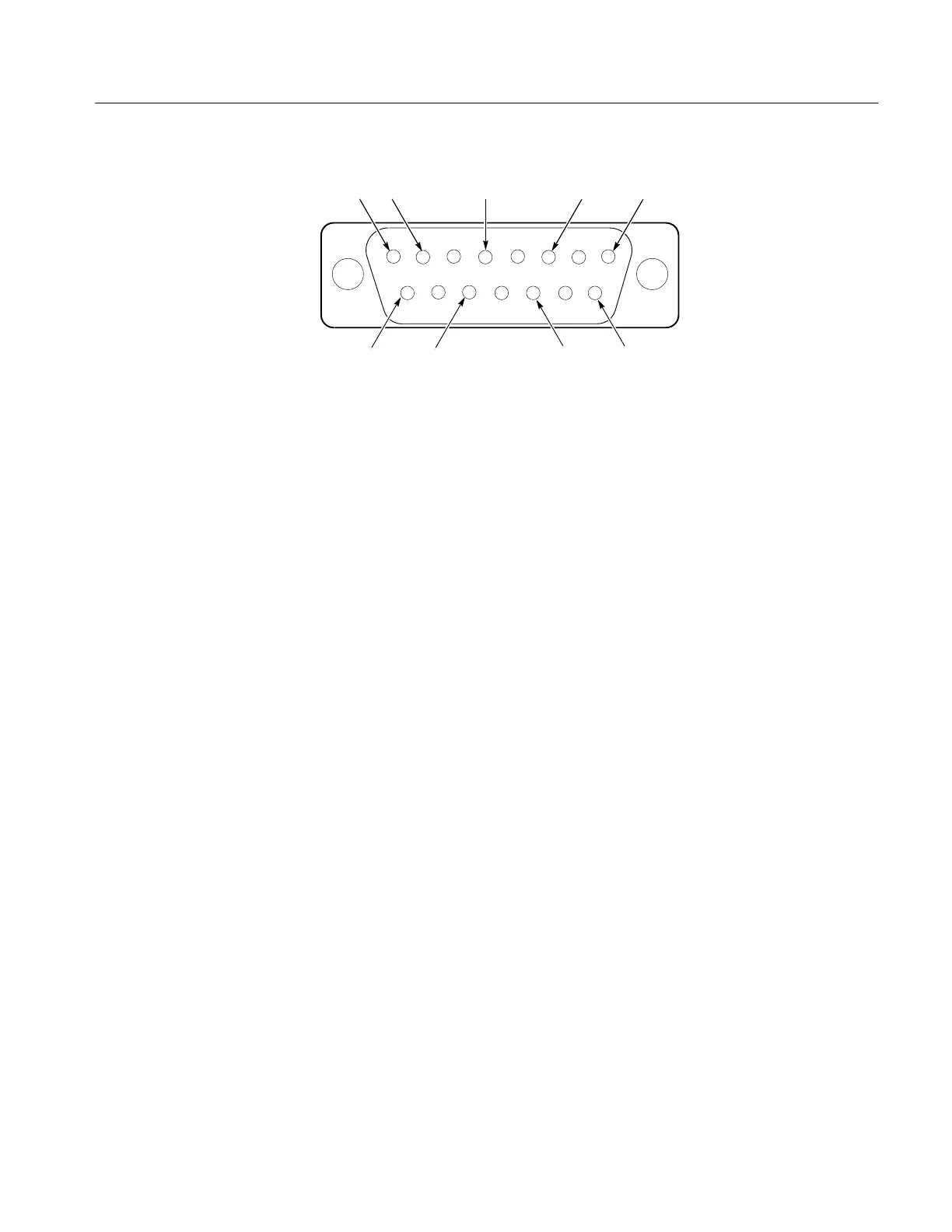
GND
GND
GND
GNDGND
GND
Not
Used
+Y
Input
–Y
Input
+Y
Input
–Y
Input
–Y
Input
+Y
High gain
input
–Y
Input
+Y
High gain
input
Figure 3-2: Rear panel XY INPUT connector showing pins with their functions.
0 dBm is equal to 1 mW or 2.19 V peak-to-peak in 600Ω.
12 dBm is equal to 15.8 mW or 8.72 V peak-to-peak in 600Ω.
Inputs can be driven single-ended by driving either the + or – X and Y inputs
with the opposite polarity inputs grounded.
In addition, a single-ended, high-gain mode can be used for other, primarily
non-audio, applications. It can be accessed by installing plug jumpers on J920
and J921 (on the Main board, see Table 3–1) and inputting the signal on the +X
and +Y inputs with the –X and –Y inputs grounded.
The rear-panel AUXILIARY connector is a 9-pin, D-type connector. It is used to
control the display from a companion 1730-Series Waveform Monitor. Line and
Field selection information is provided to the vectorscope over the bus that is
contained in this interface. Figure 3-3 and Table 3–2 show the AUXILIARY
connector pin assignments.
Auxiliary Connector