Maintenance
1720/1721
6–21
To remove front
panel assembly
To remove front
panel assembly
To separate board
from the front panel
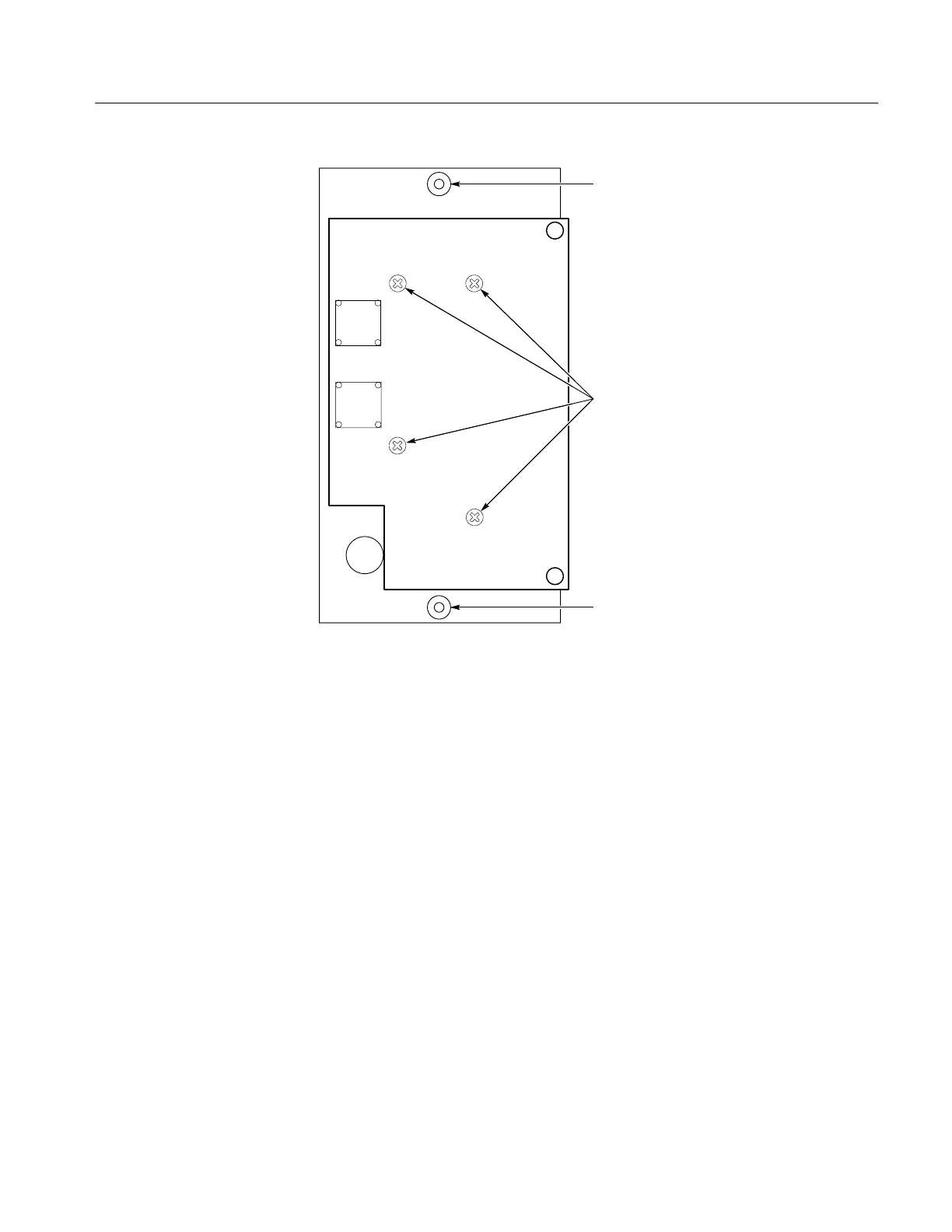
Figure 6-5: Screws that hold the Front Panel circuit board (A2) in place.
1. Remove the plugs from the following connectors: J216 to the Front Panel
board, J546 on the Power Supply board, the plug on the Phase Shifter
(Assembly A4), and J225 on the Main board (the trace rotation leads to the
crt).
2. Unsolder the leads to the six bnc connectors and three ground from the rear
panel, the two horizontal crt leads (red and green), the R–Y out, and the two
vertical crt leads (blue and brown).
3. Slip the crt and trace rotation lead through the appropriate holes in the Main
board.
4. Remove the eight screws that are holding the board in place. See Figure 6-6
for their locations.
Removing the Main Board