Theory of Operation
1720/1721
4–13
The B–Y Demodulator output is also fed back through R763 to a clamp circuit
consisting of U757 and Q761. U757 is an operational transconductance
amplifier used in a sample-and-hold circuit. The demodulated B–Y chrominance
drives the negative input (pin 2), while a voltage, controlled by the Vector
Horizontal Position control (R653), is reference level to the positive input
(pin 3).
During the middle of horizontal sync time, a pulse is applied to the bias pin of
the amplifier (pin 5), which turns the device on and transfers the voltage levels
on the – inputs to the storage capacitors C362 (for R–Y) and C761 (for B–Y).
The stored levels are applied through source followers Q362 (R–Y) and Q761
(B–Y) to the bias inputs (pin 5) of Demodulators U467 (R–Y) and U659 (B–Y).
This changes the output bias current of the demodulator to change the demodu-
lated signal dc level, which is the dc level for the Deflection Amplifier (Dia-
gram 1).
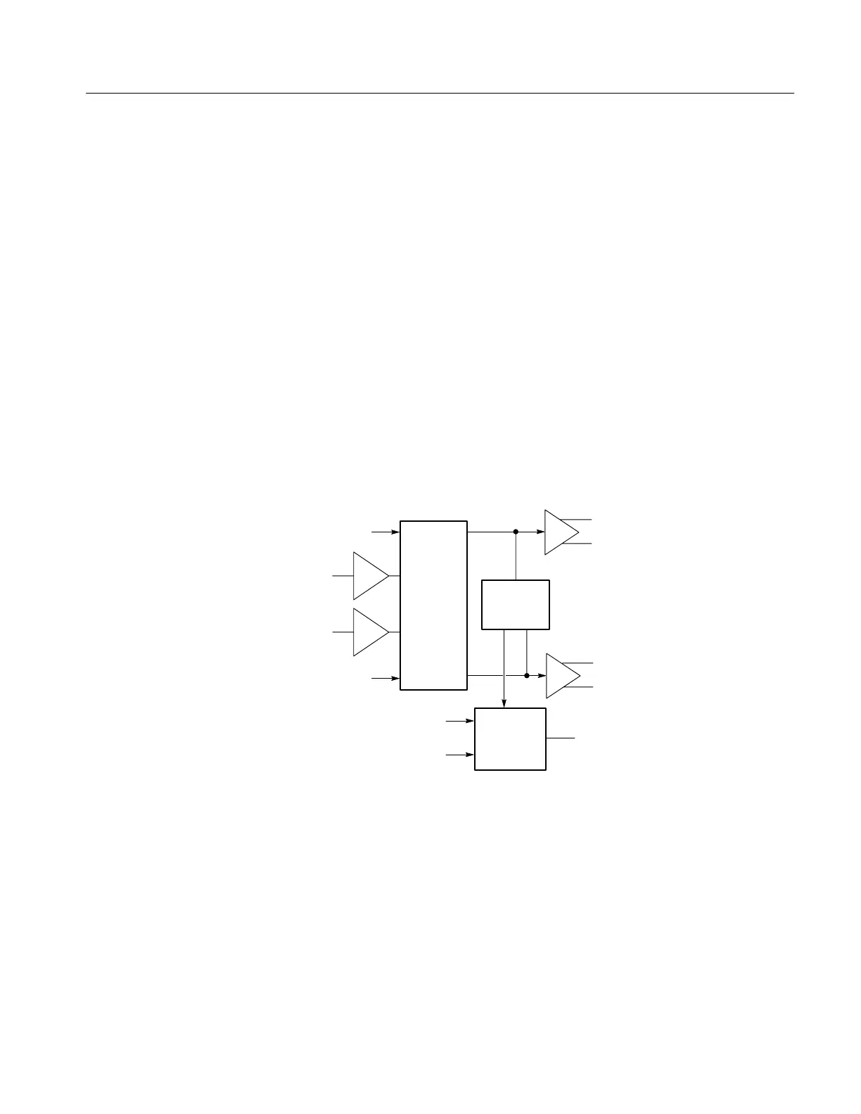
DIAGRAM 4 DEFLECTION AMPLIFIER
R–Y
B–Y
CRT Horizontal
CRT Vertical
Blanking to CRT
Line select blanking
Y Imput
X Imput
Output
switching
Center dot
comparators
m Processor blanking
CRT
blanking
External X and Y signals are input through the rear-panel sub-miniature D-type
XY INPUT connector. Output switching selects either the R–Y and B–Y or XY
for amplification and display by the Horizontal and Vertical Deflection Amplifi-
ers. Driving signals for the Deflection Amplifiers are also input, as active
driving signals for the Center Dot Comparators, to provide blanking when the crt
beam is not deflected away from center screen.
CRT blanking signals from Line Select, and the Microprocessor are combined
with the vectorscope’s H rate sync to provide the blanking signal to the grid
circuit.