Theory of Operation
1720/1721
4–11
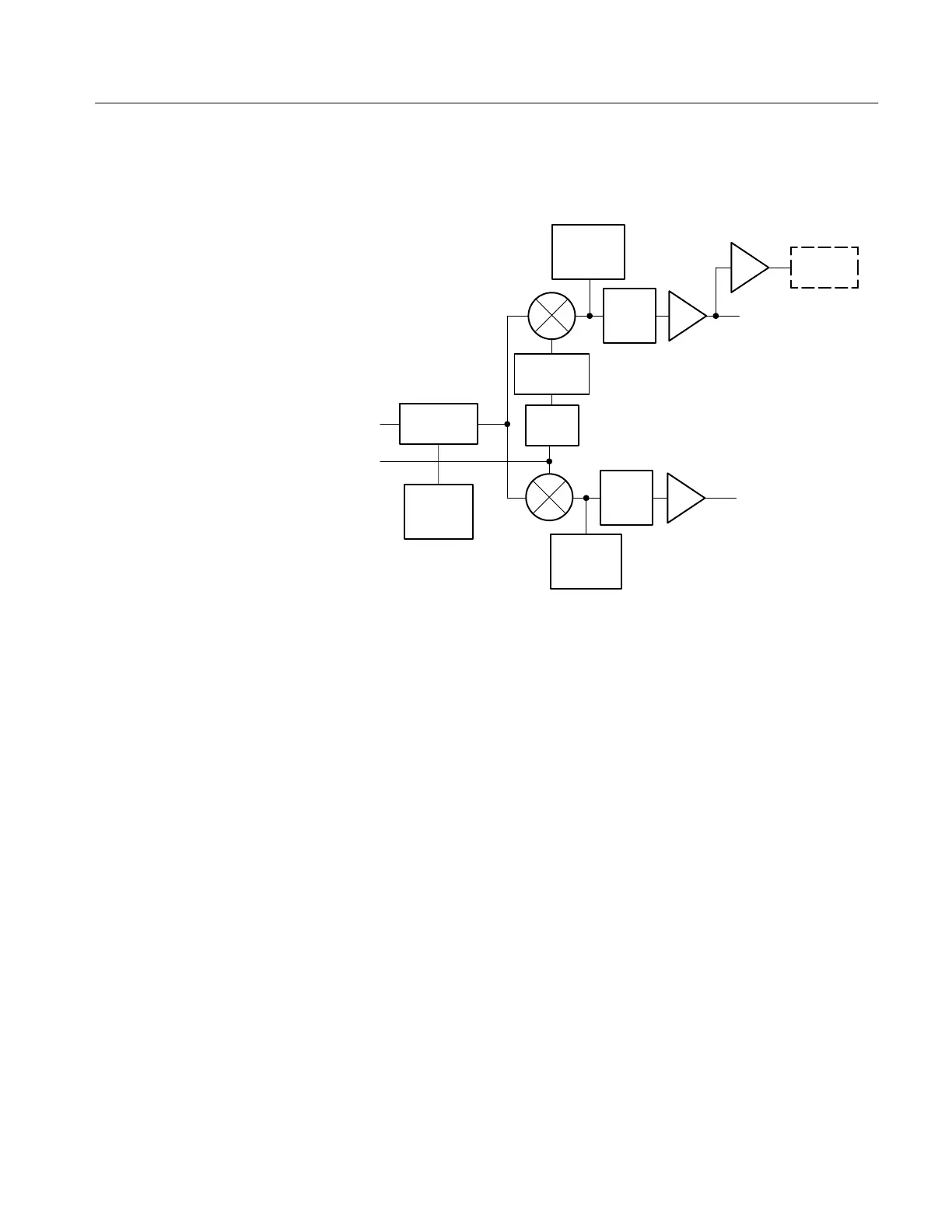
DIAGRAM 3 DEMODULATOR
CHROMA
F
SC
R-Y
(V)
B-Y
(U)
Bandpass
filter
Syc tip
chroma
clamp
Horiz
position
clamp
Low
pass
filter
Quad
phase
V Axis
switcher
Vertical
position
clamp
Low
pass
filter
DEMOD
OUT
Incoming chrominance is band-pass filtered, clamped at sync tip time, and
compared to the phase shifted regenerated subcarrier signal for demodulation.
Subcarrier signal is quadrature shifted (90°) before input to the R–Y (V)
demodulator. In addition, for PAL applications, and any time the front-panel
selected Test Circle is enabled, a V-Axis switcher shifts the subcarrier input by
180° for alternate lines.
Output signal from the Demodulators is low-pass filtered and amplified prior to
driving the Horizontal and Vertical Output Amplifiers. The output of the R–Y
(V) Demodulator is also available through the rear-panel Demodulator Output.
The V-Axis Switcher reroutes the V-Axis Demodulator carrier input on alternate
lines. In both the 1720 and the 1721, V-axis switching is enabled when the
TEST function is selected from the front panel. In the 1721, V-axis switching is
also enabled when the +V/PAL switch is in the +V position.
V-axis switching provides a display of the PAL signal that overlays the –V lines
on the +V lines. The resulting display appears as though only the +V signal is
displayed, similar to an NTSC display. This display is used to evaluate relative
differences between the +V and –V lines. This same operation occurs when the
signal is decoded in a PAL television receiver.
The Microprocessor enables V-axis switching by pulling the Preset input of
U774A (a D-type flip-flop) high, which allows the horizontal sync, clock pulses
to toggle its outputs at a line rate. The D input is controlled by another flip–flop,
V-Axis Switcher