Introduction
1–4
1720/1721
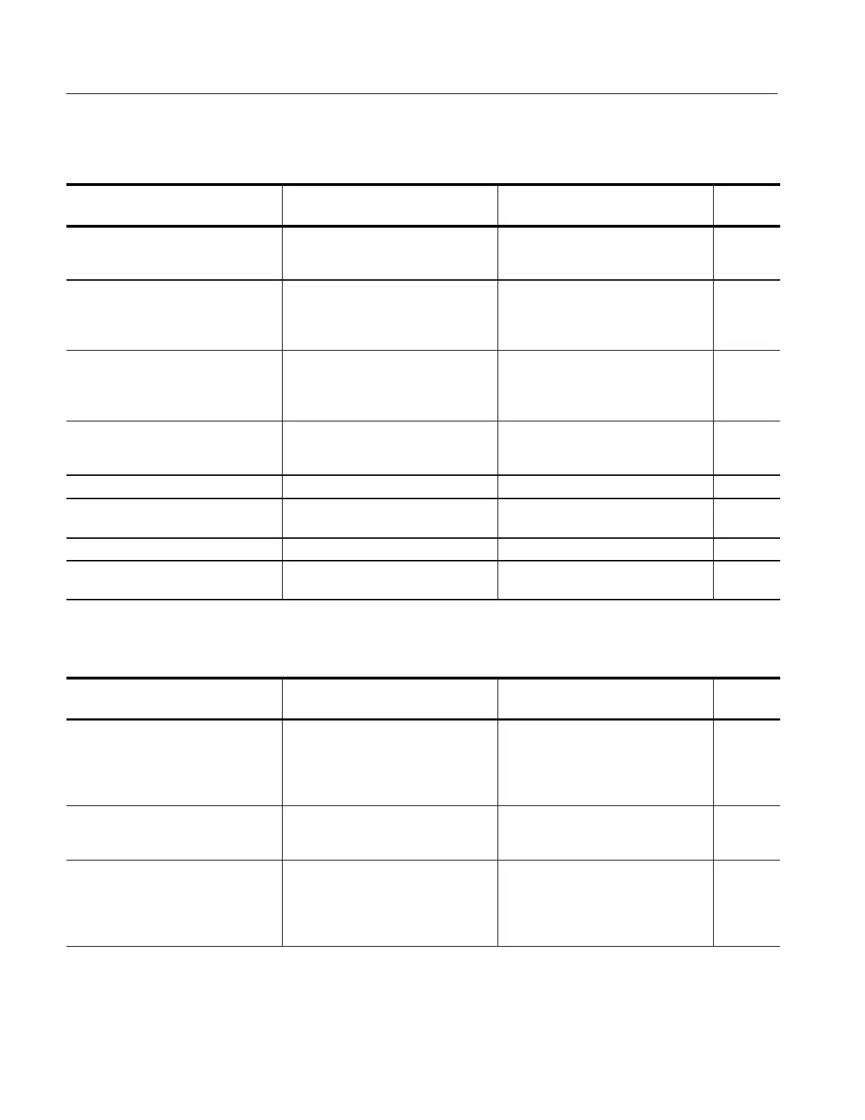
Table 1–1: Signal input
Characteristics Performance requirement Supplemental information
Step
number
Return loss (75Ω)
Video inputs (CH A, CH B)
EXT REF
At least 40 dB from 50 kHz to 6 MHz. Loop-through terminated in 75W. Input
in use or not in use, instrument power
on or off, all deflection factor settings.
11
Crosstalk between channels Greater than 70 dB of isolation be-
tween channels. Measured at F
SC
between Channel A, Channel B, and
EXT REF.
Loop-through isolation Greater than 70 dB of isolation be-
tween loop-throughs. Measured at F
SC
between Channel A, Channel B, and
EXT REF.
Input requirements Stable display with composite video, or
black burst with 286 mV (300 mV PAL)
burst ±6 dB.
3
DC input impedance (unterminated) Greater than 15 kΩ
EXT REF input Composite video (can be CW subcarr-
ier if two internal jumpers are moved).
Absolute maximum input voltage ±12 VDC plus peak AC
Maximum operating input voltage Peak AC + DC should be within
+8.0 V and –5.6 V for proper operation.
Table 1–2: Vector mode
Characteristic Performance requirement Supplemental information
Step
number
Chrominance processing characteris-
tics
Nominal subcarrier frequency (F
sc
)
NTSC
PAL
3.579545 MHz.
4.43361875 MHz.
Chrominance bandwidth
Upper –3 dB point
Lower –3 dB point
F
sc
+500 kHz, ±100 kHz
F
sc
–500 kHz, ±100 kHz
4
Display
Vector phase accuracy
Vector gain accuracy
Quadrature phasing
±1.25 Measured with color bar signal
Typically, ±2.5%
Typically, ±0.5°
5
5