Checks and Adjustments
1720/1721
5–15
Minimum
opening
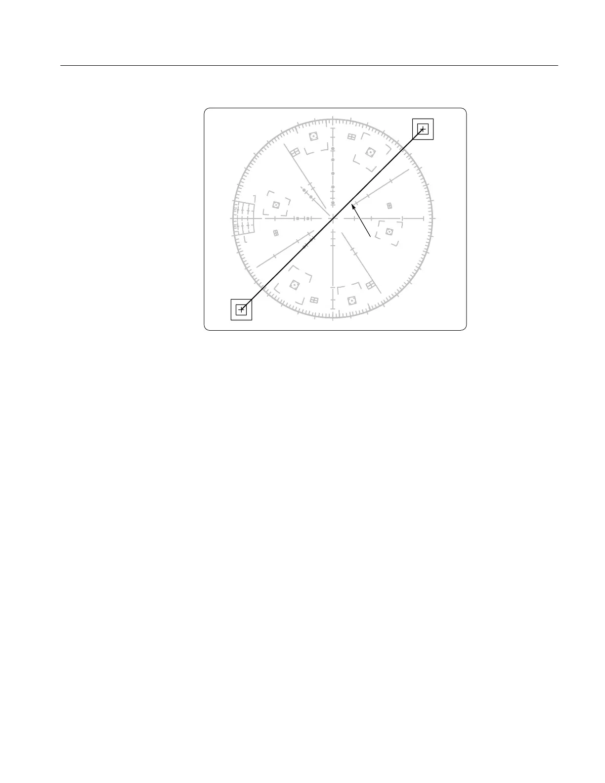
Figure 5-6: Audio frequency XY display.
14. Check XY Frequency Response
REQUIREMENT – The –3 dB point at 500 kHz or greater in standard
mode; 100 kHz or more in High Gain mode.
a. Connect the Function Generator, using the red alligator clip, to pin 3
(+X) of the 1720/1721 rear-panel XY INPUT connector. Leave the
black alligator clip connected to pins 1 and 5. See Figure 5-5.
b. Set the Function Generator frequency to 50 kHz and set its amplitude for
a display the width of the compass rose.
c. Set the Function Generator frequency to 500 kHz.
d. CHECK – that the display reaches the –3 dB gaps in the horizontal axis
or beyond. See Figure 5-3.
e. Move the Function Generator output to pin 7 (+Y) of the 1720/1721
rear-panel XY INPUT connector.
f. Set the Function Generator to 50 kHz and set its amplitude for a display
the height of the compass rose.
g. Set the Function Generator frequency to 500 kHz.
h. CHECK – that the display reaches the –3 dB gaps in the vertical axis or
beyond.