Theory of Operation
4–16
1720/1721
control lines (75%, 100%, and Variable) for instrument switching functions.
Other switching control lines are output directly from U613, ports 1 and 3. See
Table 4–1.
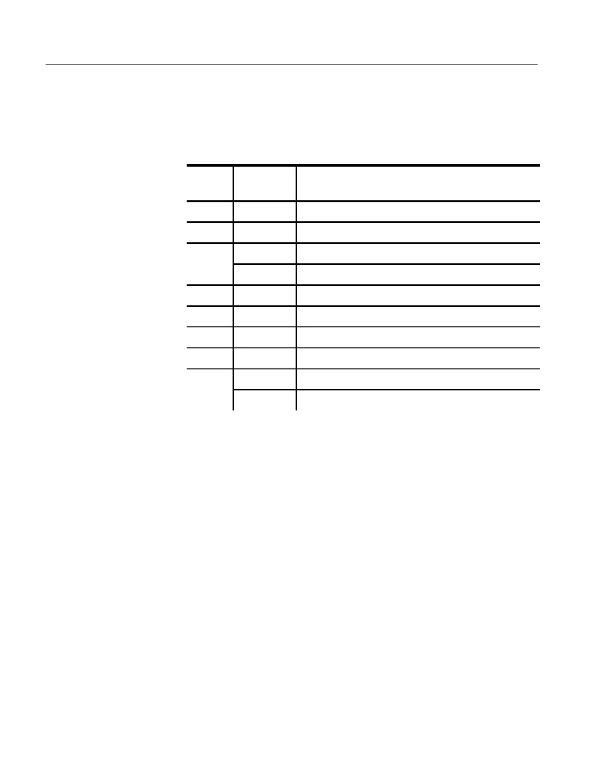
Table 4–1: U613 Switching Control Outputs
U613
PIN #
CONDITION FUNCTION
3 High Channel A Input Selected for Display
4 High Channel B Input Selected for Display
5 High Internal Reference Selected
Low External Reference Selected
6 High Vector Display Selected
7 High X Y Display Selected
8 High Test Circle Display Selected
12 Low CRT Blanked for Real Time Switching
13 High PAL (+V Switcher Off) Selected (1720 Default Mode)
Low +V (+V Switcher On) Selected
U818B is a buffer to isolate the Auxiliary port Transmit Data (TXD) from the
Microprocessor.
U613 pin 15 is the enable for buffer U818C, which allows the line select
blanking pulse from the companion 1730-Series to pass in Auxiliary mode. The
line select blanking pulse drives Q248 and Q540 in the crt Blanking circuit
located on Diagram 4.
U818D inverts the ALE pulse from the Microprocessor (pin 30) to clock U620 to
de-multiplex the address lines of the Low Address/Data bus.
U405 is the NOVRAM used to retain the current front-panel status and the
front-panel status for the Stored Recalls (Auxiliary). Data is written in and read
out through pins 3 and 4; pin 1 of U613 controls data in and out. Pin 2 of U613
provides the serial clock. Pin 14 provides the chip enable. These three lines
(Clock, Read/Write, and Chip Enable) are active when:
1. Power is turned on.
2. Any front-panel switch is pressed.
3. In Auxiliary, when a Store or Recall is requested from the companion
1730-Series.