Checks and Adjustments
5–8
1720/1721
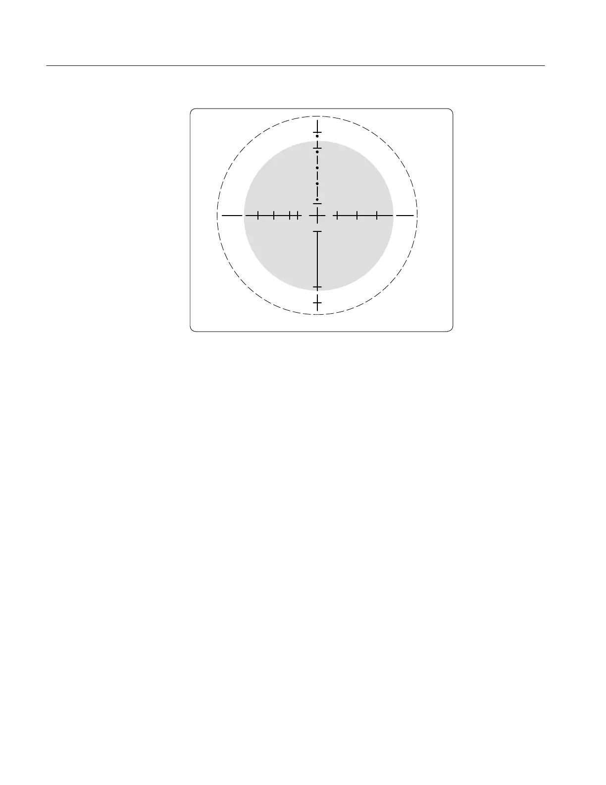
Figure 5-3: Using the vector graticule –3 dB markings to measure bandwidth.
Amplitude is set to the compass rose at the center frequency, and then as the
frequency is increased or decreased the total deflection reduces to the openings, at
the shaded inner circle, on the axes lines.
e. CHECK – that the frequency readout on the Sine Wave Generator is
between 2.98 to 3.18 MHz NTSC and PAL-M (3.83 to 4.03 PAL).
f. Repeat parts c. and d. for the horizontal graticule axis.
g. Increase the Sine Wave Generator frequency until the perimeter of the
circle touches the –3 dB (70%) point gaps on the vertical graticule axis.
h. CHECK – that the frequency readout on the Sine Wave Generator is
between 3.98 to 4.18 MHz NTSC and PAL-M (4.83 to 5.03 PAL).
i. Repeat steps g. and h. for the horizontal graticule axis.
5. Check Color Bar Decoding Accuracy
REQUIREMENT – Vector Phase accuracy within ±1.25°. Vector Gain
accuracy typically within ±1.25 IRE (NTSC or PAL-M) or ±2.5% (PAL).
a. Set the 1720/1721 REF to INT.
b. Connect the color bar to the CH-B INPUT and terminate the remaining
side of the loop-through with a 75Ω terminator. Display the signal in
VECT MODE and adjust the PHASE control to place the vector dots in
their graticule targets.

 Loading...


