Theory of Operation
1720/1721
4–17
U505 is the Power Down Detection circuit. It detects the loss of instrument
power in time for the NOVRAM (U405) to execute a save operation. When the
+5 V supply drops a few hundred millivolts, pin 7 is pulled low, which causes
U405 to Store its current status. The front-panel and Auxiliary (Store/Recall)
data is saved in a matter of milliseconds when the power starts to drop below
safe operating levels for the NOVRAM. U508 is a three-terminal regulator
operating from the +15 V supply that comes onto the circuit board from the
Power Supply circuit board. As soon as the +15 V raises enough to provide a
+5 V output from U508, U405 recalls the data saved so that it will be available
to the Microprocessor when all supplies are up to their operating tolerances.
DIAGRAM 6 CONTROL CIRCUIT
CRT Focus anode
CRT Control grid
Intens
Focus
Rotate
Scale
Focus
control
Z Axis
control
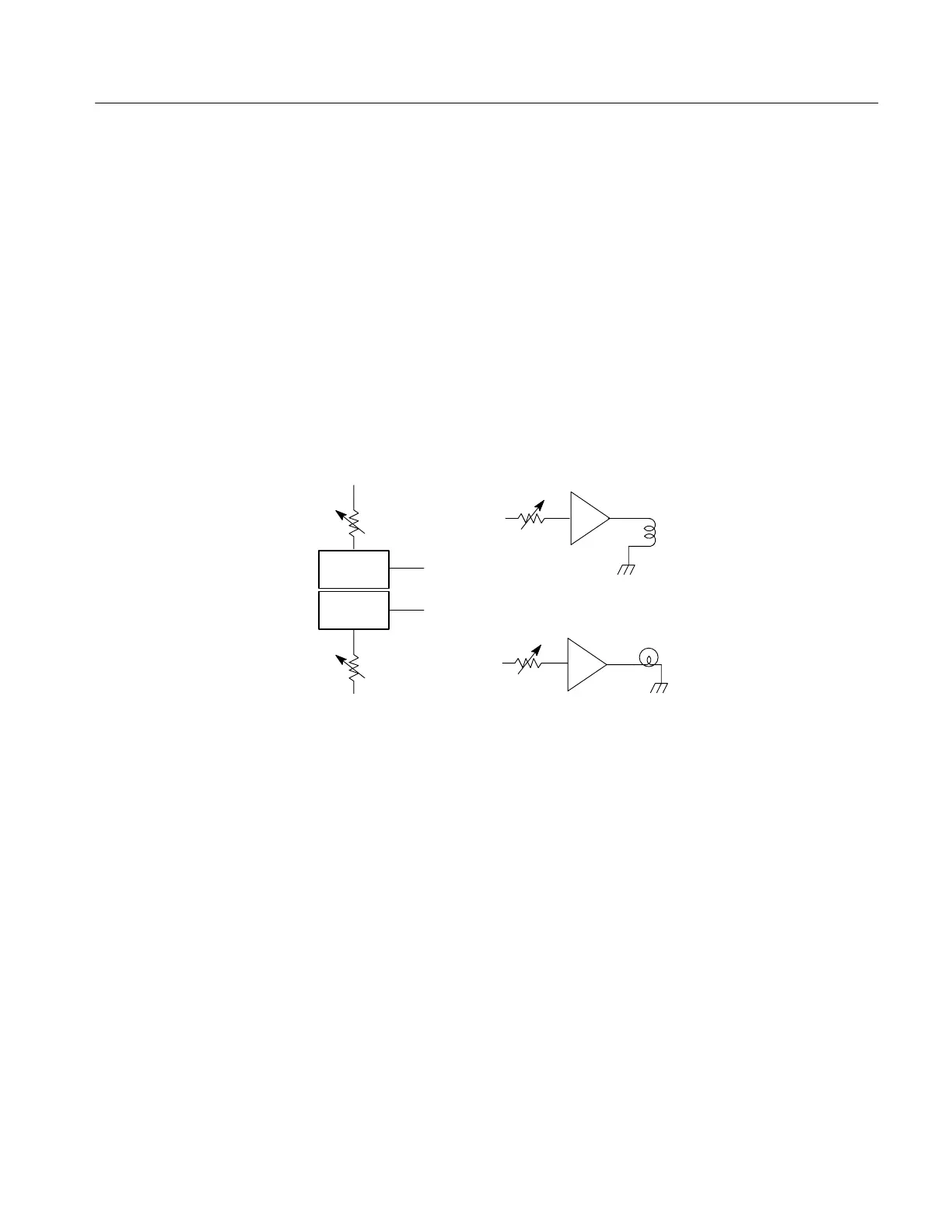
Blanking signals are input to an intensity switching matrix along with a dc
voltage level set by the front-panel INTENS control. Focus level, for the crt
focus anode, is set by regulating the current through a transistor current source.
The amount of focus current through the transistor depends on the setting of the
front-panel FOCUS control. The effects of small variations in the magnetic field
surrounding the instrument are compensated for by an adjustable magnetic field
placed around the crt bulb. Scale Illumination for the crt face plate is set by
controlling the output amplitude of a triangle generator that drives the scale
illumination bulbs.
U440 is a transistor array with two of the transistors connected as a differential
current switch. The static output current (pin 8) is set by the front-panel
INTENSITY control using Q342 as a current source. The blanking signal is
input to the switch through pin 9. When pin 9 goes high the current output
(pin 8) is shut off and the Z-Axis Amplifier (Diagram 5) blanks the crt.
In Line Select mode (which requires an external blanking pulse, input through
the Auxiliary connector, from a 1730-Series or other source) the intensity setting
Z-Axis Control