Maintenance
6–20
1720/1721
AUXILIARY CONTROL
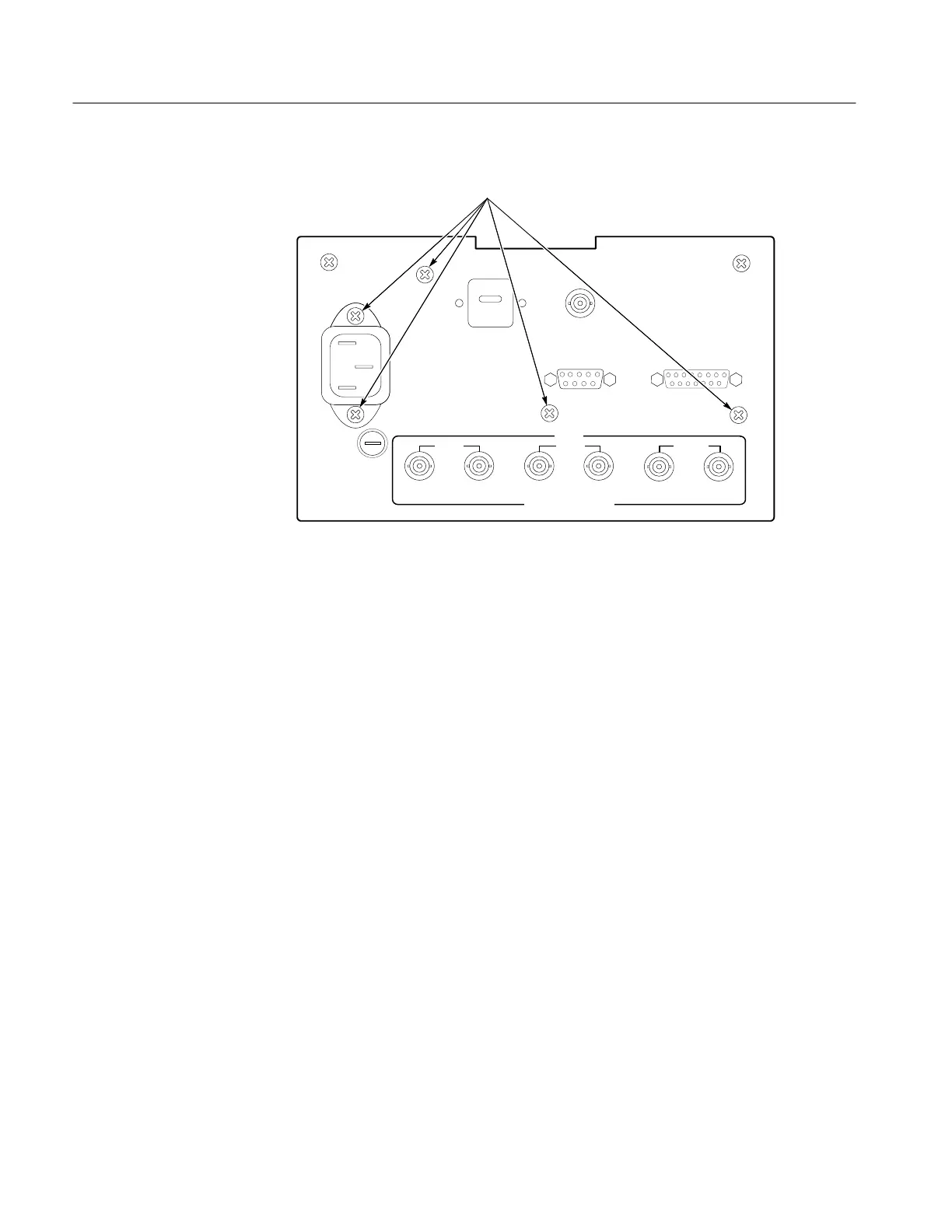
Remove these five (5)
screws to remove the rear panel.
Figure 6-4: Screws that need to be removed to remove the rear panel
1. Remove the blue multiwire connector from J154.
2. Remove the two screws holding the board in place. See Figure 6-5 for
locations.
3. Remove the board by slipping it through the front-panel opening.
4. To access the Front Panel board components:
a. Remove the knobs from the front.
b. Remove the four screws from the rear.
c. The board should now separate from the front panel making the
components accessible.
5. To re-assemble, reverse the procedure.
Removing the Front Panel
Circuit Board
 Loading...


