Operating Instructions
1720/1721
2–21
cy
MG
Q
b
U
10°
20°
30°
40°
50°
20%
5%
10°
10°
70.65°
3°
20%
60.65°
50.65°
3°
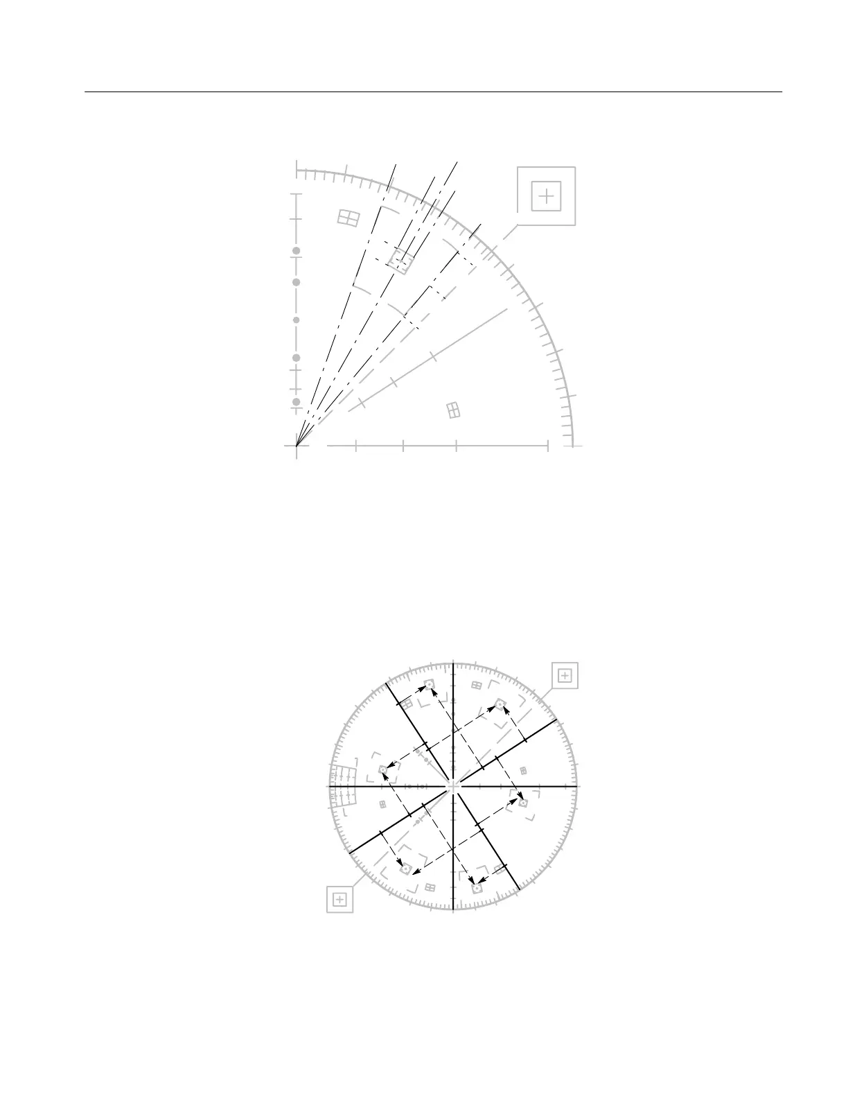
Figure 2-14: Fine detail of the 1721 graticule target.
On the 1720, the small marks at intervals along the I and Q axes denote the
amplitudes of the chrominance components (see Figure 2-15). On the 1721, the
small marks at intervals along the U and V axes denote the amplitudes of the U
and V chrominance components (see Figure 2-16).
MG
Q
B
CY
G
YL
I
R
BURST
180°
B–Y
0°
R–Y
90°
+I
123°
–Q
213°
+Q
33°
270°
–I
303°
Figure 2-15: Simulated 1720 graticule showing the relationship between amplitudes
on the I and Q modulation axes and the location of the color vector targets.