Installation
3–2
1720/1721
1
1
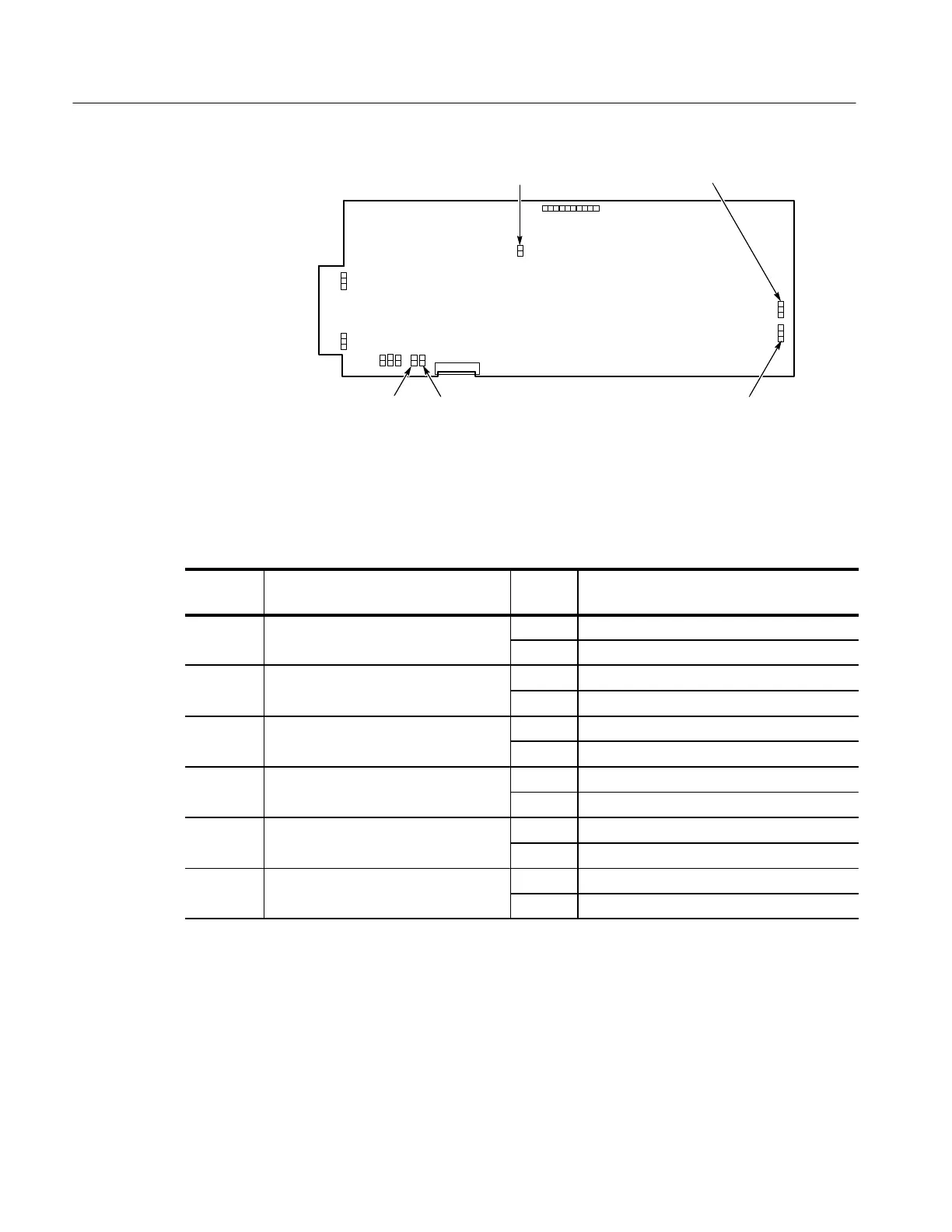
A3 Main Bd
J696 Ext sync source
J796 Subcarrier refJ921 X High gainJ920 Y High gain
J245 Blanking disable
Front
Figure 3-1: Plug jumper locations. A small arrow on the board, next to the plug
jumper, denotes pin 1.
Table 3–1: Internal Jumper Selection
Jumper
Number
Name Position Purpose
3J696 External Sync Source (EXT REF Input) 1-2 EXT REF (factory preset)
Converted to CW Subcarrier Input 2-3 CH-A INPUT
3J796 Subcarrier Reference 1-2 EXT REF (factory preset)
2-3 CW Subcarrier applied to EXT REF INPUT
3J920 Y Input High Gain Out Balanced 600W input (factory preset)
In Single-ended high gain mode
3J92
X Input High Gain Out Balanced 600W input (factory preset)
In Single-ended high gain mode
3J245 Blanking Disable Out Normal Blanking (factory preset)
In CRT Blanking disabled
3
J
00 Light Enable 1-2 Lights Enabled (factory preset)
2-3 Lights Disabled

 Loading...


