Checks and Adjustments
5–14
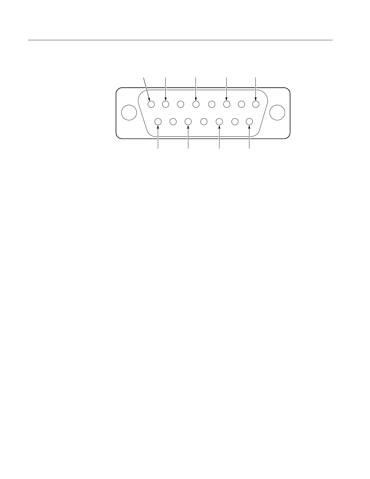
1720/1721
12345678
9101112131415
+Y
INPUT
+Y HIGH
GAIN INPUT
–X
INPUT
+X
INPUT
–Y
INPUT
+X HIGH
GAIN INPUT
–Y
INPUT
–X
INPUT
GND GND GND
GND GND GND
Not
used
Figure 5-5: Rear-panel XY INPUT connector showing inputs.
g. CHECK – that either end of the trace can be moved >1° (one-half minor
division on the compass rose) either direction from horizontal.
h. Set ROTATE so that the trace is on the horizontal axis.
13. Check XY Input Phase Matching
REQUIREMENT – Less than a trace width of separation at 100 kHz.
a. Connect the Function Generator output to both pins 3 (+X) and 7 (+Y)
of the XY INPUT connector, using the red alligator clip. Leave the
black alligator clip connected to pins 1 and 5. See Figure 5-5.
b. Set the Function Generator frequency to 10 kHz and adjust its amplitude
so that the trace extends between the targets (+) on the diagonal line.
c. Set the Audio Signal Generator frequency to 100 kHz.
d. CHECK – that there is a trace width or less separation in the diagonal
display. See Figure 5-6.