Theory of Operation
1720/1721
4–3
front-panel indicators are driven by the Microprocessor so that they will mirror
the current measurement criteria.
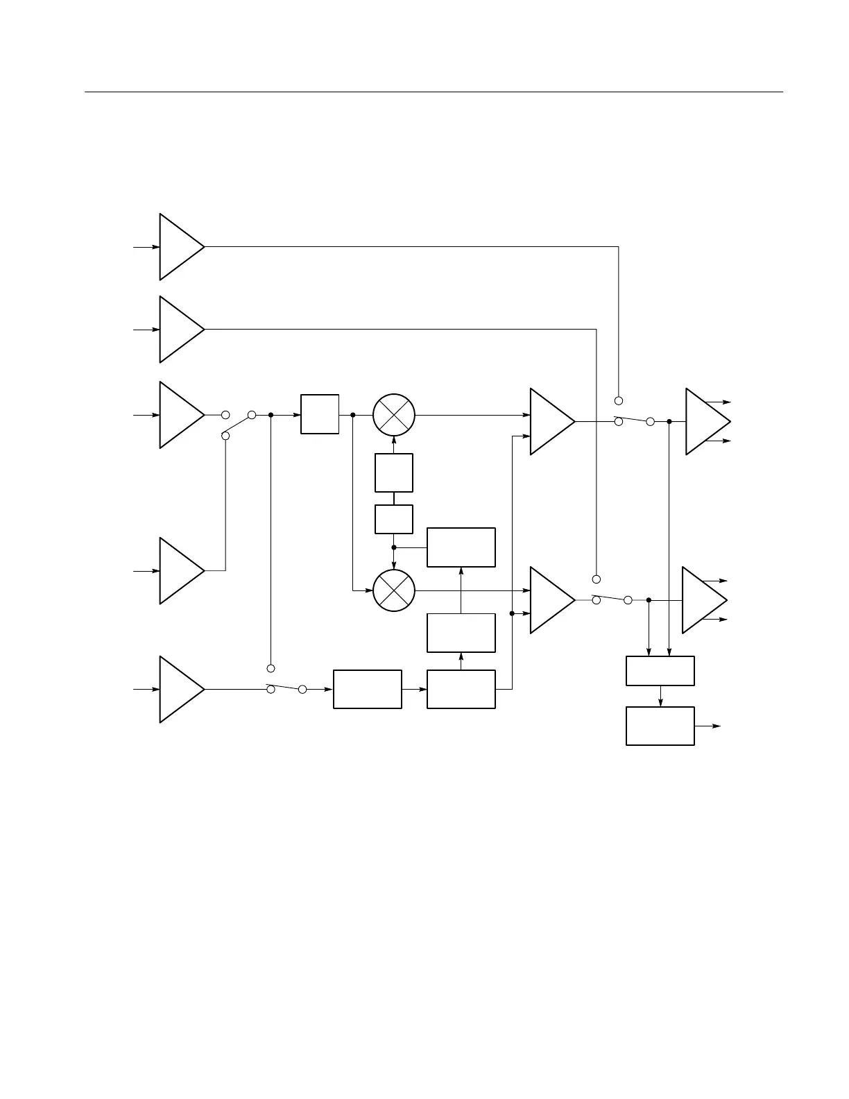
CH A
CH B
EXT REF
Gain
180°
Flip
90°
X Input
Y Input
Sync
stripper
Clamp
generator
Subcarrier
regenerator
Phase
shifter
To CRT
Vertical
deflection
plates
To CRT
Horizontal
deflection
plates
To CRT
Detectors
Center dot
blanking
Blanking
Figure 4-1: Simple block diagram of a 1720/1721 Vectorscope.
The gain cell uses front-panel VAR GAIN and GAIN CAL settings and
switching signals from the Microprocessor to adjust the chrominance gain prior
to demodulation. Gain cell chrominance is clamped to ground at sync tip time
for a stable reference level.
Chrominance from the incoming video signal, either internal or from the
External Reference, is conditioned by the Chrominance Amplifier and applied to
the Phase Detector at burst time (Burst Gate signal). The chrominance input to
Gain Cell
Chrominance Processing