1720/1721
2–1
Section 2
Operating Instructions
These instructions provide information about the front-panel controls, rear-panel
connectors, the Operator’s Familiarization/Checkout Procedures, and discussions
about vector and audio measurements using the 1720/1721.
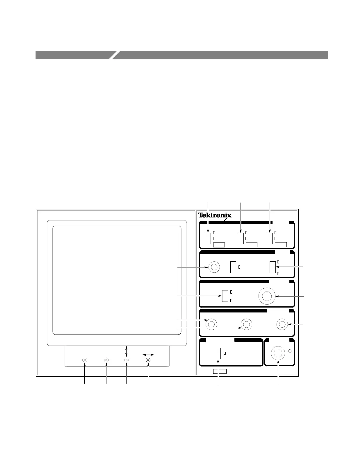
Front-Panel Controls and Indicators
The front-panel controls and indicators consist of momentary contact push-but-
ton switches, variable controls, and backlit switch selections. See Figure 2-1 for
the control and indicator locations.
INPUT
DISPLAY
MODE
ON
REF
GAIN
PHASE
= HOLD FOR FUNCTION
FOCUS SCALE INTENS
ON
BOTH
VECT
X Y
INT
EXT
TEST
75%
100%
CH–A
CH–B
VARIABLE BARS
PAL
+V
POWER
ROTATE
GAIN
CAL
BOTH
ON
1
4
5
12
13
14
6
8
7
9
10
11
2
3
15 16
VECTOR
SCOPE
172X
AUXILIARY
Figure 2-1: Control and indicator locations.