Theory of Operation
1720/1721
4–15
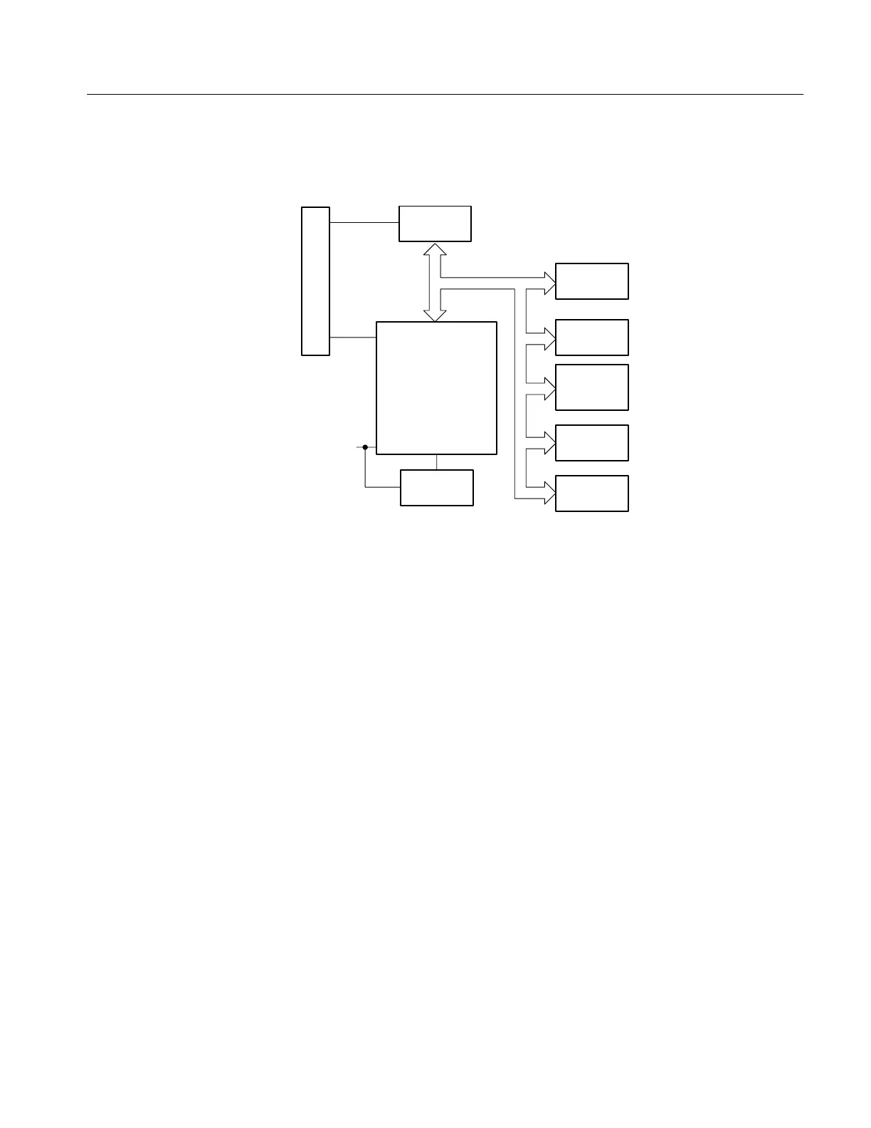
DIAGRAM 5 MICROPROCESSOR
Front panel
controls
Auxiliary control in
Buffer
Microprocessor
Readout drive
Address
Demux
I/O Data
switch
Switch control
LED Drive
NOVRAM
Operation of the 1720/1721 is controlled by the Microprocessor. It controls
switching operation by either polling the front-panel switches, or in response to
stored/recalled front-panel configurations (Auxiliary Input from a companion
1730-Series).
In addition, the Microprocessor drives the front-panel indicator light-emitting
diodes through a light driver.
A Non-Volatile Random Access Memory (NOVRAM) retains the current
operating state in the event of power interruption, including operator power
down.
The 1720/1721 is controlled by a ROM-based Microprocessor. U613 is an 8-bit
Microcontroller that operates either with U624 (early serial numbers, a 4k X 8
EPROM) or contains its own masked ROM. Pins 32 through 39 of U613
(AD0–AD7) is a multiplexed address and data bus. U620 de-multiplexes the
lower address bus for program code retrieval, in early serial numbers. U613
controls switching in response to front-panel keyboard action. Front-panel
switches are ground closures and are buffered by U311, an octal buffer. When
the front panel is to be read, pin 17 of U613 goes low to enable U311, which
outputs the front-panel key status to the data bus. In addition, a serial bus
structure, through U818A, is input to U613 through pin 10. This is the Auxiliary
bus for operation with a companion 1730-Series.
U315 and U319 are the front-panel LED drivers. The front-panel LEDs light
when the light driver outputs are low. In addition, U319 pins 6, 9, and 12 are
Microprocessor