Removal and Installation Procedures
6-24
CSA7404B, TDS7704B, TDS7404B, TDS7254B & TDS7154B Service Manual
b. Grasp the top of Front-Panel assembly and pull forward to allow access
to the ribbon-cable connector on the front-panel board.
c. Use the
1
8
inch flat-bladed screwdriver to carefully lift the J1 cable
connector lock up to disconnect the J1 flex cable from the display
module assembly. See Figure 6--10, page 6--25. Note the pin 1 index
mark and the black stripe on the cable for later reassembly.
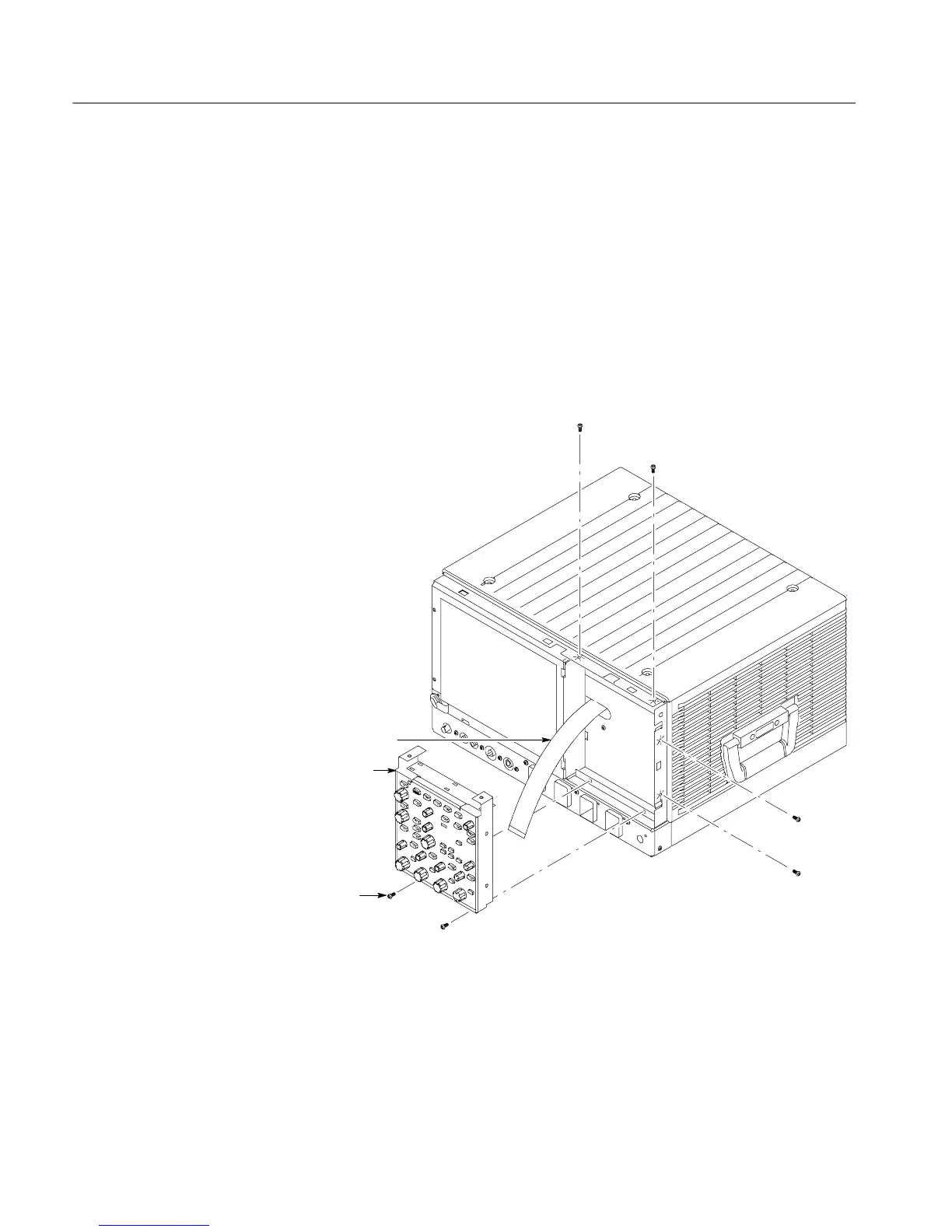
d. Pull the Front-Panel assembly forward and remove from the instrument.
4. Reinstallation: Do in reverse steps a through d to reinstall the front-panel
assembly.
T-15
Torxdrive
screw (6)
Front panel
assembly
J1 ribbon cable
Figure 6- 9: Front-panel assembly removal

 Loading...


