Removal and Installation Procedures
CSA7404B, TDS7704B, TDS7404B, TDS7254B & TDS7154B Service Manual
6-25
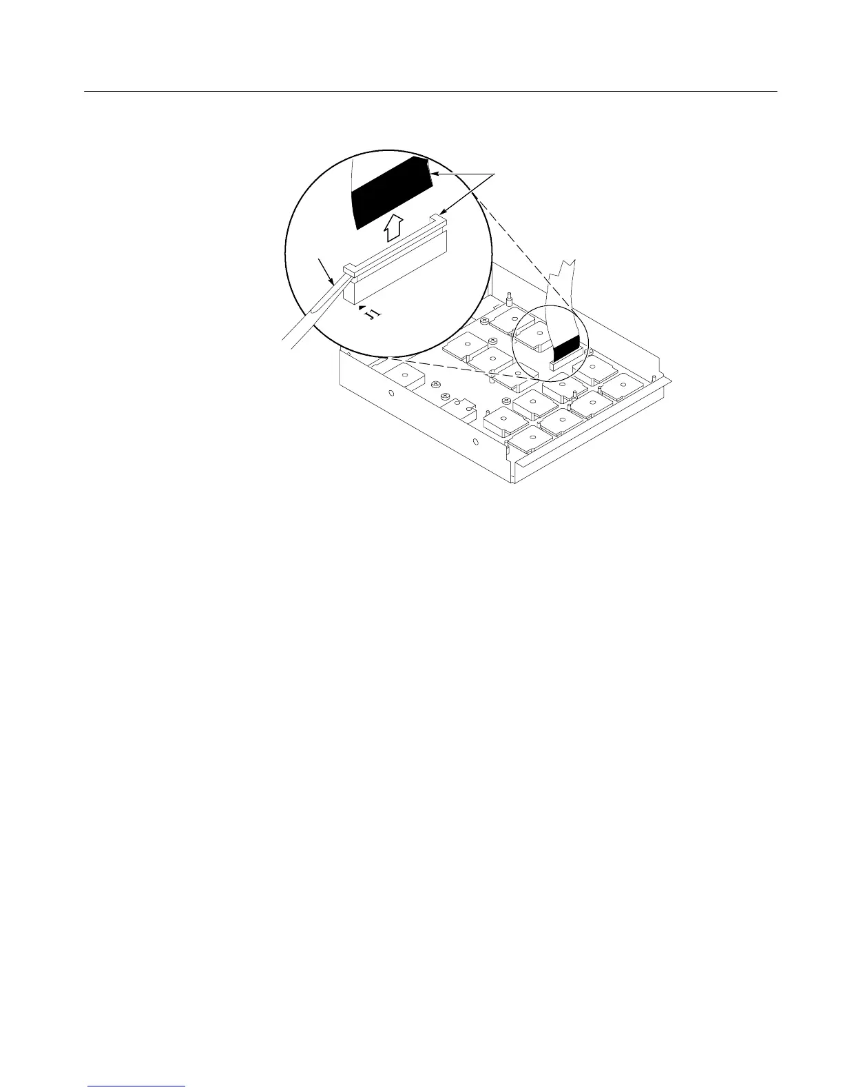
Screwdriver
Black stripe
toward connector
Figure 6- 10: J1 flex cable connector r emoval
1. Locate module to be removed: Locate the Front Panel assembly Figure 6--9,
page 6--24. Additional modules to be Removed:
H Front Panel Knobs
H Trim (front panel)
H Front Panel assembly
2. Remove the Front Panel board: SeeFigure6--11,page6--26.
a. Remove the eight T-15 Torxdrive screws that secure the Front panel
board to the Front panel assembly.
b. Remove the board from the assembly.
3. Reinstallation: Do in reverse steps a through b to reinstall the front panel
board.
Front Panel B oard

 Loading...


