Service and Repair Manual June 2021
Manifolds
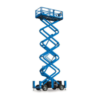
90 GS
™
-84 • GS
™
-90 Part No. 1306587GT
11 Adjust the internal hex socket. Turn it
clockwise to increase the pressure or
counterclockwise to decrease the pressure.
Install the relief valve cap.
12 Repeat this procedure beginning with step 7.
13 Fully lower the platform.
14 Using a suitable lifting device, add an
additional weight to the platform not to exceed
20% of the maximum rated work load at full
height. Secure the weight to the platform.
Refer to the specifications below.
-3384 and GS-3390
500 l
227 k
-4390
- refer to capacity indicator
375 l
170 k
-4390
- refer to capacity indicator
450 l
204 k
-5390
375 l
170 k
15 Activate the platform up function and attempt
to raise the platform.
Result: The platform does not raise. Proceed
to step 21.
Result: The platform lifts. Proceed to step 16.
16 Lower the platform to the stowed position.
17 Turn the machine off. Hold the system relief
valve with a wrench and remove the cap.
18 Adjust the internal hex socket. Turn it
counterclockwise to decrease the pressure.
Install the relief valve cap.
19 Start the engine.
20 Repeat this procedure beginning with step 15.
21 Turn the machine off and remove the weight
from the platform.
How to Adjust the St eer Relief Valve
How to Adjust the Steer Relief
Valve
Note: Refer to Function Manifold Component list to
locate the steer relief valve.
1 Connect a 0 to 3000 psi / 0 to 250 bar
pressure gauge to the test port (item AB) on
the function manifold.
2 Start the engine from the platform controls.
3 Press and hold the function enable switch and
hold the steer thumb rocker switch in the right
direction. Allow the wheels to completely turn
to the right, then continue holding the switch
while observing the pressure reading on the
pressure gauge. Note the pressure. Refer to
Specifications, Hydraulic Component
Specifications.
4 Turn the engine off. Use a wrench to hold the
relief valve and remove the cap (item AE).
5 Adjust the internal hex socket. Turn it
clockwise to increase the pressure or
counterclockwise to decrease the pressure.
Install the relief valve cap.
-over hazard. Do not adjust
the relief valve higher than
sp
ecified.
6 Repeat steps 2 through 3 to confirm the relief
valve pressure.
 Loading...


