June 2021 Service and Repair Manual
Hydraulic Pump
Part No. 1306587GT GS
™
-84 • GS
™
-90 75
6-1
Lift/Steer Pump
Note: When removing a hose assembly or fitting,
the O-ring (if equipped) on the fitting and/or hose
end must be replaced. All connections must be
torqued to specification during installation. Refer to
Specifications, Hydraulic Hose and Fitting Torque
Specifications.
How to Remove the Lift /Steer Pump
How to Remove the Lift/Steer
Pump
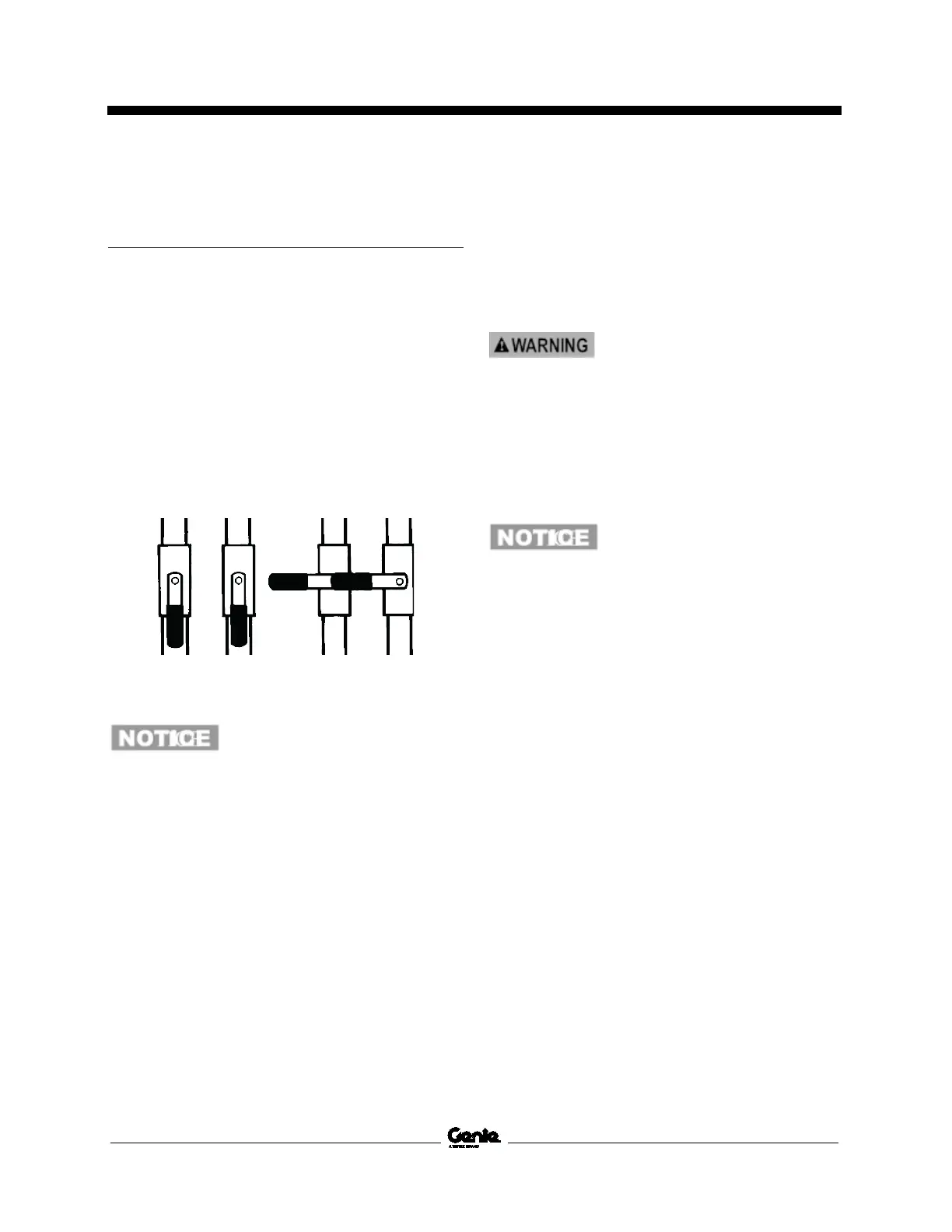
1 Locate the three hydraulic tank valves at the
hydraulic tank. Close the valves.
open closed
Component damage hazard.
The engine must not be started
with the
hydraulic tank shut-off
valves in the closed position or
component damage will occur. If
the tank valves are closed,
remove the key from the key
switch and tag the machine to
inform personnel of the
condition.
Note: The hydraulic tank shutoff valves can be
accessed from under the hydraulic tank tray.
2 Release the latches on the engine tray and
fully slide the engine tray out.
3 Insert a 6 inch / 15 cm screwdriver or rod into
the engine tray lock hole located near the
engine tray roller wheels to prevent the
engine tray from moving.
4 Tag, disconnect and plug the hydraulic hoses
from the lift/steer pump . Cap the fittings on
the pump.
Bodily injury hazard. Spraying
hydraulic oil can penetrate and
burn skin. Loosen hydraulic
connections very slowly to all
ow
o dissipate
gradually. Do not allow oil to
squirt or spray.
5 Remove the pump mounting fasteners.
Carefully remove the pump.
Component damage hazard. Be
sure to open the two hydraulic
tank valves and prime the pump
after installing th
e pump.

 Loading...


