June 2021 Service and Repair Manual
Scissor Components
Part No. 1306587GT GS
™
-84 • GS
™
-90 41
75 Place a rod through each chassis centering
link pivot pin and twist to remove the pin. Rest
the centering links on the chassis.
76 Remove the pin retaining fasteners from the
number 1 inner arm slide blocks (index #31)
at the steer end of the machine.
77 Use a slide hammer to remove the number
1 inner arm slide block pivot pins (index #31).
78 Use a slide hammer to remove the number
1 outer arm slide block pivot pins (index #31)
at the non-steer end of the machine.
79 Carefully remove the number 1 inner and
outer arms (index #14 and #16) from the
machine.
rushing hazard. The number
inner and outer arms could
become unbalanced and fall
when they are removed from
the machin
e if not properly
supported by the overhead
crane.
Note: If further disassembly of the scissor arm pair
is required, refer to Repair Procedure, How to
Disassemble a Scissor Arm Pair.
How to Disassemble a Sc issor Arm Pair
How to Disassemble a Scissor
Arm Pair
Bodily injury hazard. This
procedure requires
specific repair
skills, lifting equipment and a
suitable workshop. Attempting
this procedure without these
skills and tools could result in
death or serious injury and
significant component damage.
Deale
r service is strongly
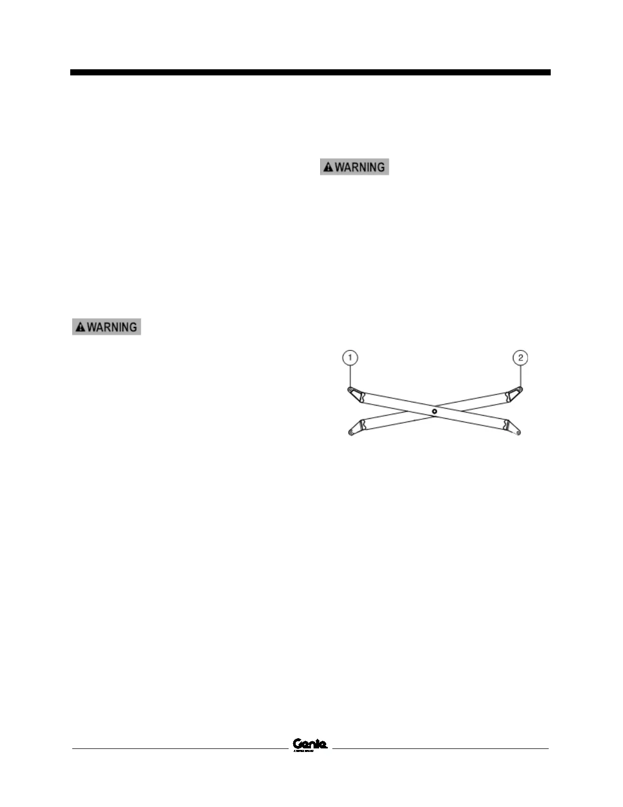
1 Attach a lifting strap from an overhead crane
to the end of the outer arm.
Note: Attach the lifting strap to the end of the
scissor arm that has the casting pointing upwards.
1 outer arm
2 inner arm
2 Attach a lifting strap from a second overhead
crane to the end of the inner arm.
Note: Attach the lifting strap to the end of the
scissor arm that has the casting pointing upwards.
3 Raise the scissor arms with the overhead
cranes approximately 12 inches / 30 cm.
 Loading...


