Service and Repair Manual June 2021
Scissor Components
30 GS
™
-84 • GS
™
-90 Part No. 1306587GT
14 Use a soft metal drift to remove the lift
cylinder rod-end pivot pin (index #17). Lower
the rod end of the lift cylinder down.
Crushing hazard. The lift
cylinder could fall if not properly
supported when the pin is
removed.
15 Block the steer end wheels and center a lifting
jack of ample capacity under the non-steer
end of the drive chassis.
16 Loosen the wheel lug nuts on one of the non-
steer wheels. Do not remove them.
17 Raise the machine approximately 2 inches /
5 cm. Place blocks under the chassis for
support.
ssis
will fall if not properly supported.
18 Remove the wheel lug nuts. Remove the tire
and wheel assembly.
19 Tag, disconnect and plug the hydraulic hoses
from the lift cylinder. Cap the fittings on the
cylinder.
Bodily injury hazard. Spraying
hydraulic oil
can penetrate and
burn skin. Loosen hydraulic
connections very slowly to allow
the oil pressure to dissipate
gradually. Do not allow oil to
squirt or spray.
20 Cut the zip ties attaching the hydraulic hoses
to the lift cylinder. Lay the hoses out of the
way.
Component damage hazard.
Hoses can be damaged if they
are kinked or pinched.
21 Remove the cables from the number 3 inner
arm (index #18) and lay the cables off to the
side.
damage hazard.
Cables can be damaged if they
are kinked or pinche
d.
22 Remove the pin retaining fasteners from the
cable tray pivot pin at the number 3 inner arm.
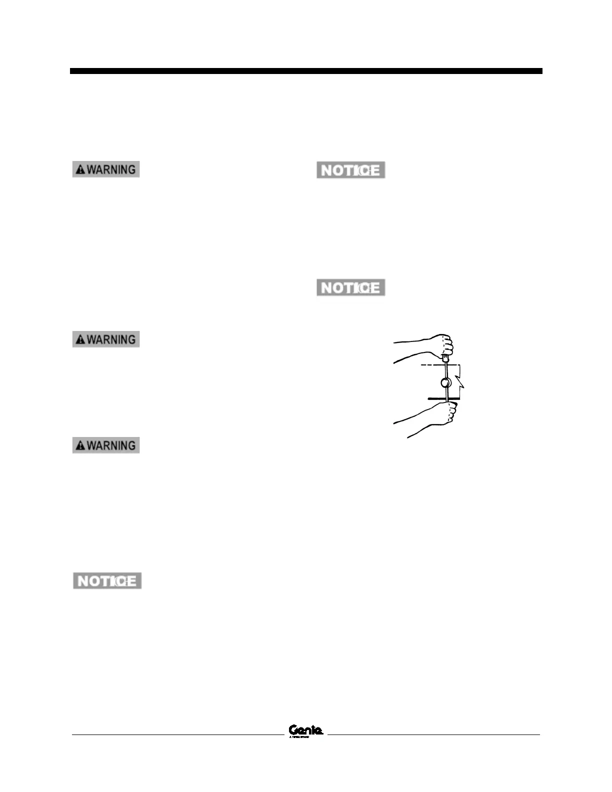
23 Place a rod through the cable tray pivot pin
and twist to remove the pin. Lower the cable
tray down.
Component damage hazard.
Cables can be damaged if they
ar
e kinked or pinched.
24 Secure both ends of the number 3 inner and
outer arms (index #18 and #16) together with
a strap or other suitable device.
25 Attach a lifting strap from an overhead crane
to the number 3 inner and outer arms (index
#18 and #16) at the steer end of the machine.
Do not apply any lifting pressure.
26 Attach a lifting strap from an overhead crane
to the number 3 inner and outer arms (index
#18 and #16) at the non-steer end of the
machine. Do not apply any lifting pressure.
27 Remove the pin retaining fasteners from both
number 3 pivot pins (index #6) at the non-
steer end of the machine. Do not remove the
pins.
 Loading...


