Hours Min.
Procedure:
Table: 003
GTH-4017EX
GTH-4514EX
GTH-4013EX
November 2008 Section 7 - Repair Procedures
TABLE 003
Document 57.0009.0427
11
GTH-4017EX GTH-4514EX GTH-4013 EX
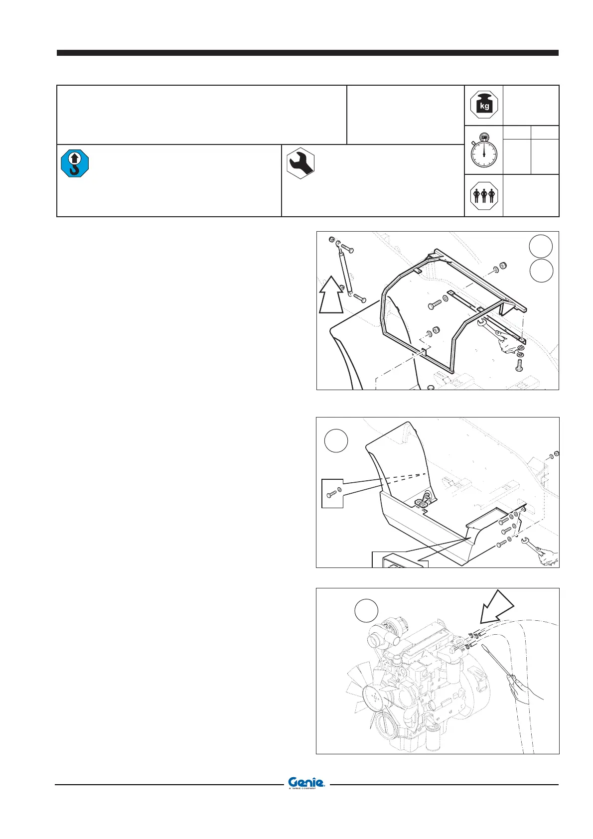
Removing the engine from the
machine
Bridge crane, payload 500 kg
Textile bridles or chains with hooks
Standard tools
340
2 30
2
Operation:
1 Open the engine cover.
2 Secure the engine cover to a bridge crain using
a textile bridle.
3 Using two 13mm wrenches, remove the two
screws of the spring (A).
4 Again with two 13mm wrenches, loosen the five
screws (B) that secure the cover to the frame of
the machine.
5 Remove the upper cover.
6 Disconnect the two battery leads and remove
the battery using a 13mm wrench and a 4mm
Allen wrench; remove the two screws of engine
fuse box using a 10mm combination wrench.
7 Using two 17mm wrenches, remove the six
screws fixing the lower cover of the engine.
8 Remove the lower cover using a stacker.
9 With a screwdriver, disconnect the fuel feeding
and return piping held in position by the special
hose-clamps.
3
4
7
A
B
9
 Loading...