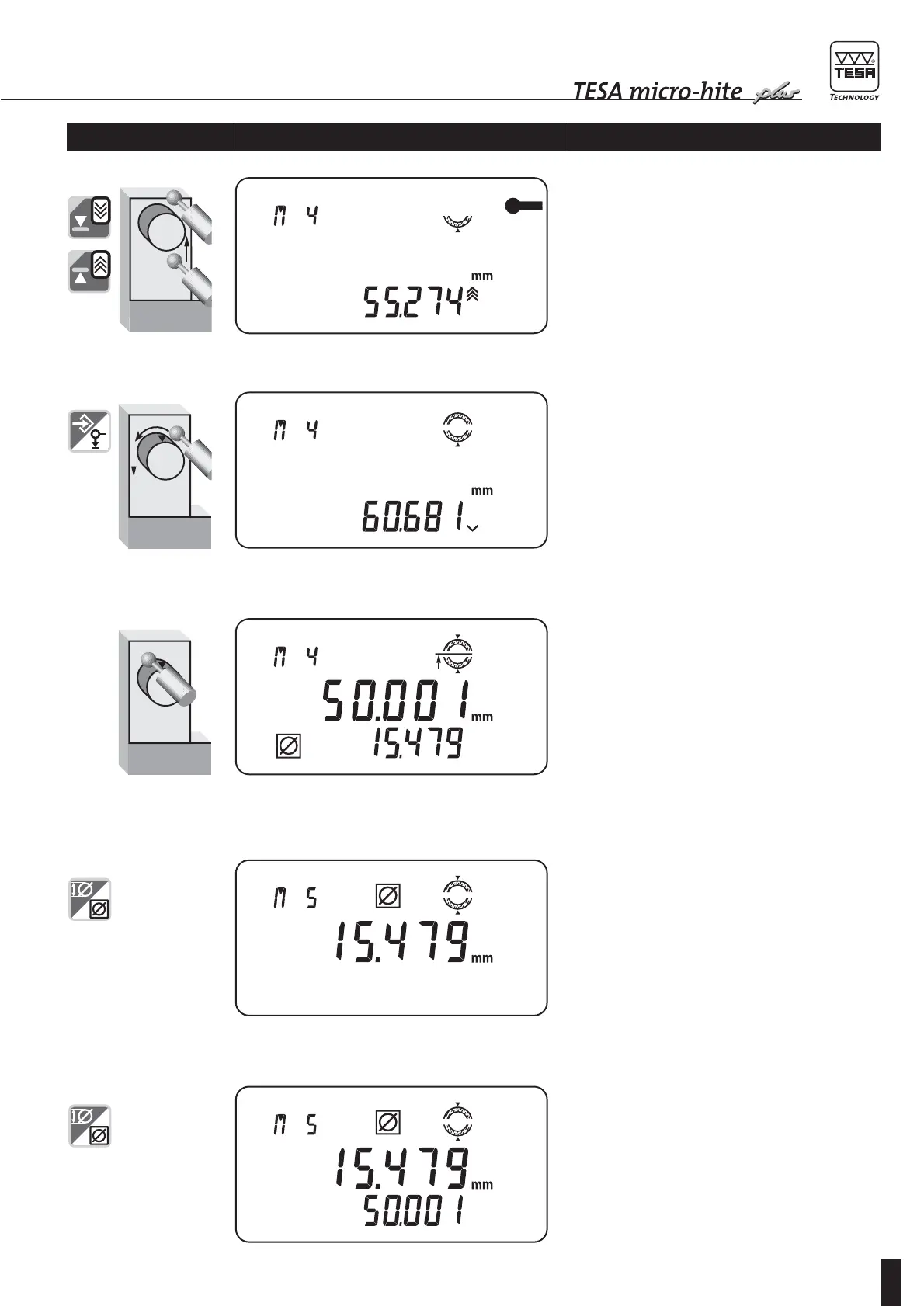
4 Once first measurement cycle has been completed,
probe insert moves clear of the workpiece automat-
ically, then stands still. Use both relevant keys or
the rotary power control for correct positioning of
the insert above the given diameter.
5 Start second measurement cycle by pressing
ENTER or rotating the power control.
Display shows probe insert moving down, continu-
ously. From then on, proceed as for the first meas-
urement cycle.
6 Second measurement cycle is completed.
Measured values are normally displayed.
7 Main display shows the difference between both
probe contacts for a while. Numbered value is
incremented providing dip switch 6 is set on ON.
8 Display shows the difference between both probe
contacts permanently. Displayed values are not
retained in memory once the height gauge has been
switched off.
Enabling keys/gauge Displaying Explanation