4.16
Measuring perpendic-
ularity errors using
a dial test indicator
Each TESA Micro-hite plus M is adjusted mechani-
cally so that any deviation from perpendicularity
(frontal) can be established with use of a dial test
indicator (e.g. TESATAST). For this purpose, the
indicator will be mounted on the probe-holder
N° 00760222 which, in turn, will be clamped on the
height gauge. The measurement is taken by moving
the measuring carriage vertically using the rotary
power control while reading out both maximum and
minimum deviations captured by the indicator.
4.17
Measuring perpendic-
ularity and straight-
ness errors using a
TESA IG-13 digital
probe
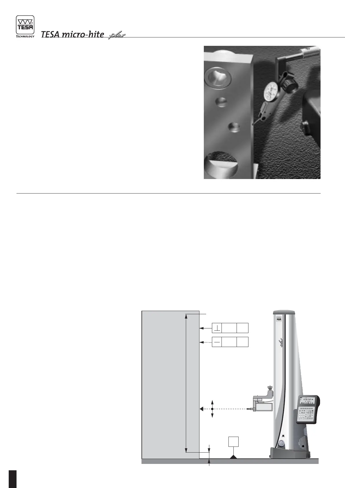
The TESA IG-13 digital probe has been specially
designed for use in association with a TESA
MICRO-HITE in standard execution for measuring
form and position errors. This probe mainly serves
for measuring any deviation from perpendicularity
and straightness. It cannot be used in conjunction
with a TESA Micro-hite plus M unless it is linked to
the Power Panel plus M. The measuring configura-
tion is pictured in Fig. 1.
TESA IG-13 incorporates an opto-electronic meas-
uring system which includes a precision glass scale
with incremental divisions.
Measuring span 13 mm / 0.51 in
Signal resolution 0.0005 mm
Accuracy 1 µm
Measuring force 0,45 N (at zero)
0,75 N (at stop)