Preparing the measurements
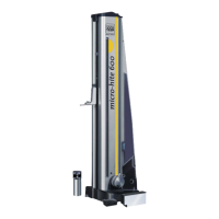
TESA IG-13 should always be used in conjunction
with the attachment N° 00760138, which will then
be fixed to mounting pin 4. The connecting cable is
plug into the socked at the rear of the Power Panel
plus M using the 1 m long cable extension N°
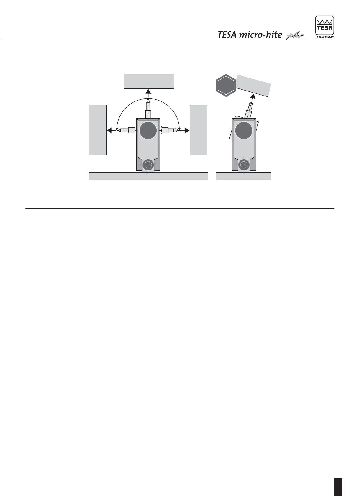
04761047. There are several ways to position the
probe with its attachment as shown in both Fig. 1
and 2. Whenever perpendicularity and straightness
errors are determined according to Fig. 1, the
measurements can be carried out in either of the
following directions: «frontal», «lateral on the left»
or «lateral on the right». Therefore, each TESA
Micro-hite plus M is capable to compensate for bias
errors automatically. For more details with regard to
this, read in chapter 3.7.
The automatic value correction as programmed in
the electronics (EEPROM) will only be active with
connected digital probe clamped in one of the three
lock-in positions as shown in Fig. 2. The correction
values stored in the memory are different for both
directions «frontal» and «lateral».
If a lock-in position is not respected or another
measuring instrument such as a dial test indicator
is used, the automatic correction remains inactive.
In this case, the perpendicularity error as measured
on your TESA Micro-hite plus M will match the limit
values stated in chapter 7 – Technical data.
Fig. 3
Three lock-in positions
for correct positioning
of the TESA IG-13
digital probe.
frontal
lateral on the
left side
lateral on the
right side
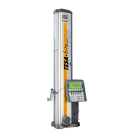
– Mount TESA IG-13 probe on the holder, then
clamp to the mounting pin located on the vertical
column.
– Connect the cable to the socket at the rear of the
Power Panel plus M using the cable extension
N° 04761047.
– Initialise TESA IG-13 once mounted and properly
connected before starting measuring. This is
done by retracting the measuring bolt against the
limit stop, manually.
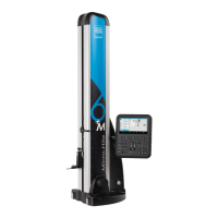
Your Power Panel plus M is specially programmed
for value processing and displaying. To know more
about the probe contact procedure, report to the
manual specific to this feature.
When measuring perpendicularity and straightness
errors according to Fig. 1, the maximum speed
used for retracting TESA IG-13 shall not exceed
20 mm/s. Therefore, we recommend to use the
rotary power control.
Measuring