17
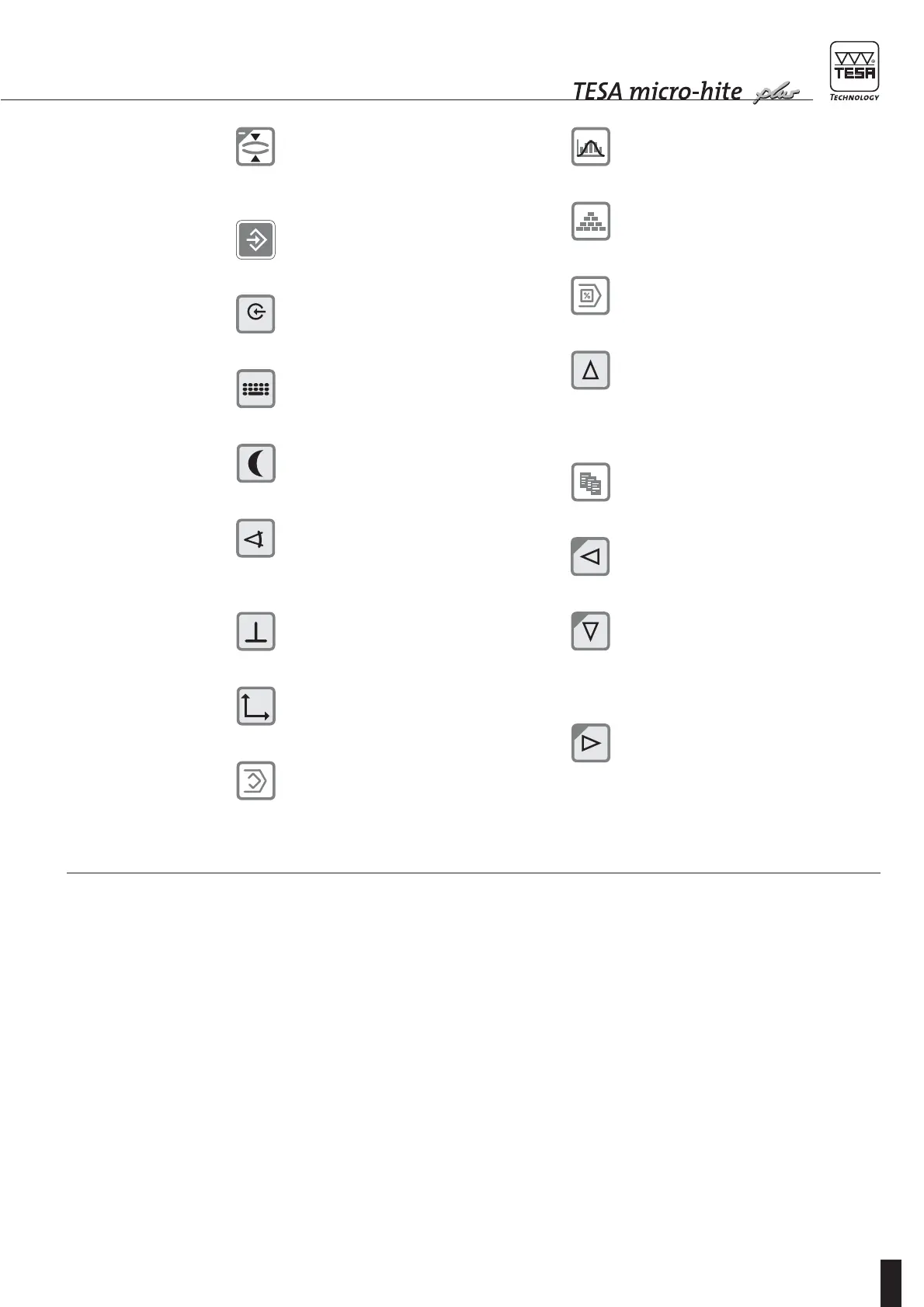
Press to measure both the centre and
diameter of a shaft.
Press ENTER to validate your operation.
Press for value capture from the measur-
ing instrument connected to RS port.
Press to input a value via the keyboard.
Press to activate idle mode.
Press to access mode for angle measure-
ment.
Press to access mode for perpendicular-
ity measurement.
Press to access 2D measuring mode.
Press to create a learn programme.
Press to enter in statistics menu.
Press to enter in configuration menu.
Press to enter in menu for executing
a programme.
When pressed in measuring mode:
let you access to logbook and have the first
5 values displayed.
Also allows the cursor to move up by one
position or one field.
Press to enter in menu for generating data
files.
Press to move cursor to the left by one
position or one field.
When pressed in measuring mode:
let you access to the logbook and have the
last 5 values to come be displayed.
Also allows the cursor to move down by
one position or one field.
Press to move cursor to the right by one
position or one field.
4.4
Probing procedure
at the contact point
In order to guarantee the reliability of the measured
values, the following condition has to be met:
ensure that the probe is firmly fixed on fixing arm 5,
which is clamped on mounting pin 4. Also check
that both knurled screws of the probe holder are
fully tighten.
As you are fitting the insert, be sure it is not pushed
beyond the stop that comes first (start of spring
travel) before clamping tight. Since the spring force
will act over a distance of 1 mm approximately, the
guiding part of the measuring head is thus pro-
tected against shocks
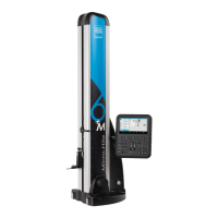
Each Power Panel plus M comes with an additional instruction manual.