20
4.5
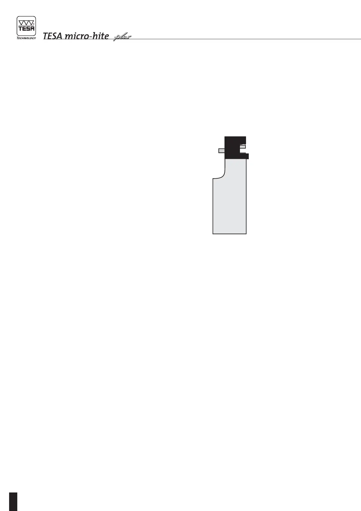
Establishing probe
constant for length
measurements with
inversion of the
probing direction
Whenever bores, shafts, grooves and the like are
measured with inversion of the probing direction,
the probe constant has to be taken into account.
To allow you carrying out your measurements with-
out any time-consuming calculation, this constant
is determined on a reference standard whose actual
dimension is known – in this case the master piece
N° 00760219 that came with your height gauge.
This gauge block combination matches the internal
or external size of 6,350 mm / .25000 in.
Note
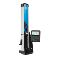
– Use only the master piece marked with number
00760219 that came with TESA Micro-hite plus
M. Its serial number is identical to that of the
height gauge.
– Final inspection also refers to this master piece.
Same goes for the SCS calibration certificate pro-
vided with the height gauge.
This piece has been specially designed for use with
TESA Micro-hite plus M. The reason for this new
feature was to reduce the error resulting from the
calibration of the inserts having a 5 mm diameter or
smaller. The external part allows the constant of
longer inserts to be determined.
The probe constant, which is a permanent correc-
tion factor, is computed by the control panel once
the probing operations on the master piece have
been completed. The value obtained is then stored
in the memory and automatically taken into account
for any subsequent measurement.
The probe constant makes allowance or compen-
sates for the following:
–True diameter of the ball tip or disc of the probe
insert used.
– Elasticity of the probe with mounted insert under
the action of the measuring force.
– Hysteresis of the measuring system.
Should the measuring conditions be changed, the
probe constant must be determined afresh.
Main reasons for changes are:
– whenever the height gauge is switched off;
– when probe insert has been exchanged;
– when insert position has been altered.
The function «Establishing probe constant»
requires at least 2 probe contacts at each point. The
difference between both values obtained at each
point must be equal to the given limit value which
depends on the selected resolution. Should this
value be exceeded, display shows the difference
value which can either be accepted or the system
asks for the contact operations to be repeated.