Timer 3 and Timer 4 Registers
www.ti.com
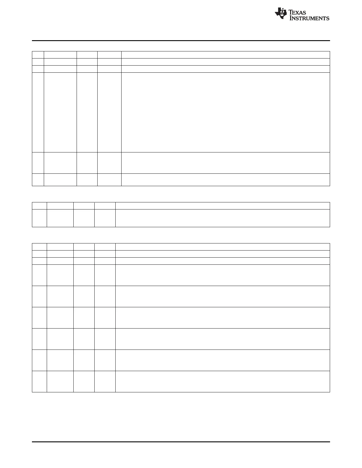
T4CCTL1 (0xEE) – Timer 4 Channel 1 Capture/Compare Control
Bit Name Reset R/W Description
7 – 0 R0 Reserved
6
IM
1 R/W Channel 1 interrupt mask
5:3
CMP[2:0]
000 R/W Channel 1 compare output-mode select. Specified action on output when timer value equals
compare value in T4CC1
000: Set output on compare
001: Clear output on compare
010: Toggle output on compare
011: Set on compare-up, clear on compare-down in up-down mode. Otherwise, set output on
compare, clear on 0.
100: Clear output on compare-up, set on compare-down in up-down mode. Otherwise clear
output on compare, set on 0.
101: Set output on compare, clear on 0xFF
110: Clear output on compare, set on 0x00
111: Initialize output pin. CMP[2:0] is not changed.
2
MODE
0 R/W Mode. Select Timer 4 channel 1 mode
0: Capture mode
1: Compare mode
1:0
CAP[1:0]
00 R/W Capture mode select. 00 – No Capture, 01 – Capture on rising edge, 10 – Capture on falling
edge, 11 – Capture on both edges
T4CC1 (0xEF) – Timer 4 Channel 1 Capture/Compare Value
Bit Name Reset R/W Description
7:0
VAL[7:0]
0x00 R/W Timer capture/compare value, channel 1. Writing to this register when T4CCTL1.MODE = 1
(compare mode) causes the T4CC1.VAL[7:0] update to the written value to be delayed until
T4CNT.CNT[7:0] = 0x00.
TIMIF (0xD8) – Timer 1/3/4 Interrupt Mask/Flag
Bit Name Reset R/W Description
7 – 0 R0 Reserved
6
OVFIM
1 R/W Timer 1 overflow interrupt mask
5
T4CH1IF
0 R/W0 Timer 4 channel 1 interrupt flag
0: No interrupt is pending.
1: Interrupt is pending.
4
T4CH0IF
0 R/W0 Timer 4 channel 0 interrupt flag
0: No interrupt is pending.
1: Interrupt is pending.
3
T4OVFIF
0 R/W0 Timer 4 overflow interrupt flag
0: No interrupt is pending.
1: Interrupt is pending.
2
T3CH1IF
0 R/W0 Timer 3 channel 1 interrupt flag
0: No interrupt is pending.
1: Interrupt is pending.
1
T3CH0IF
0 R/W0 Timer 3 channel 0 interrupt flag
0: No interrupt is pending.
1: Interrupt is pending.
0
T3OVFIF
0 R/W0 Timer 3 overflow interrupt flag
0: No interrupt is pending.
1: Interrupt is pending.
132
Timer 3 and Timer 4 (8-Bit Timers) SWRU191C– April 2009–Revised January 2012
Submit Documentation Feedback
Copyright © 2009–2012, Texas Instruments Incorporated