Operation
www.ti.com
20.1.4.2 Master Mode
The I
2
C module is configured as an I
2
C master by setting the I2CCFG.ENS1 and I2CCFG.STA bits. When
the master is part of a multi-master system, its own address must be programmed into the
I2CADDR.ADDR register. The value of the I2CADDR.GC bit determines whether the I
2
C module responds
to a general call.
20.1.4.2.1 I
2
C Master Transmitter Mode
To enable master transmit mode, set the I2CCFG.ENS1 and I2CCFG.STA bits. The I
2
C module then
waits until the I
2
C bus is free. When the I
2
C bus is free, it generates a START condition, sends the slave
address, and transfers a transmit direction bit. It then generates an interrupt, and the first byte of data can
be written to the I2CDATA register. The I
2
C core sends I2CDATA content if arbitration is not lost, and then
generates another interrupt. The I2CSTAT register contains a value of 0x18 or 0x20, depending on the
received ACK bit (see Table 20-3). If a not-ACK is received from the slave, the master must react with
either a repeated START condition or a STOP condition. Setting I2CCFG.STA during transmission causes
a repeated START condition to be transmitted. Setting I2CCFG.STO during transmission causes a STOP
condition to be transmitted and the I2CCFG.STO bit to be reset.
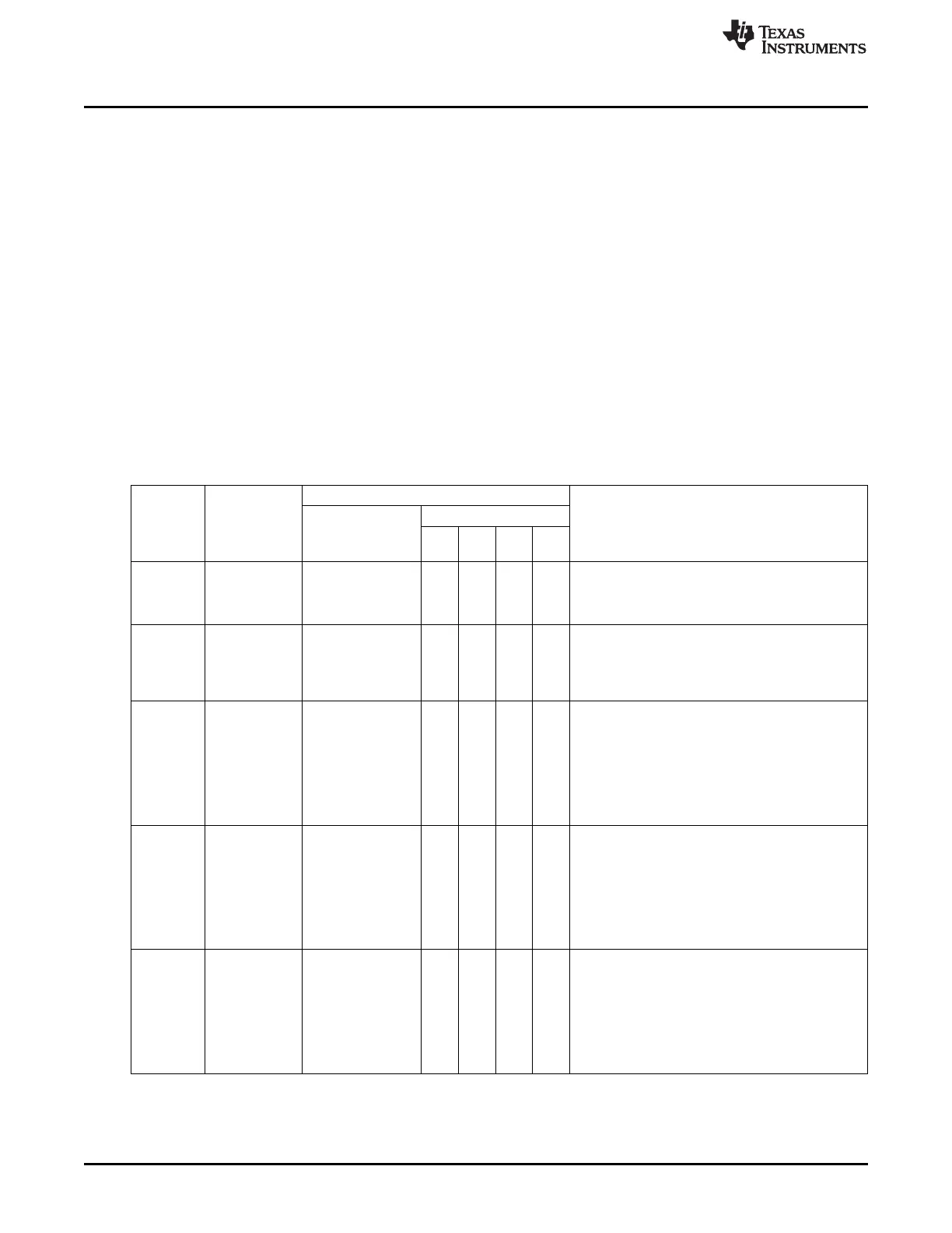
Table 20-3 provides more details regarding the master transmitter operation.
Table 20-3. Master Transmitter Mode
Status Application Software Response
Code
To I2CCFG
Status of the
(Value of Next Action Taken by I
2
C Hardware
I
2
C
To/From I2CDATA
I2CSTAT.
STA STO SI AA
STAC)
0x08 A START Load SLA+W X 0 0 X SLA+W is transmitted.
condition has ACK is received.
been
transmitted.
0x10 A repeated Load SLA+W X 0 0 X As for START condition (0x08)
START
or X 0 0 X SLA+W is transmitted; I
2
C is switched to MST/REC
condition has
load SLA+R mode.
been
transmitted.
0x18 SLA+W has Load data byte 0 0 0 X Data byte is transmitted; ACK is received.
been
or 1 0 0 X Repeated START is transmitted.
transmitted;
no action
ACK has been
or 0 1 0 X STOP condition is transmitted; STO flag is reset.
received.
no action
or 1 1 0 X STOP condition followed by a START condition is
no action transmitted; STO flag is reset.
0x20 SLA+W has Load data byte 0 0 0 X Data byte is transmitted; ACK is received.
been
or 1 0 0 X Repeated START is transmitted.
transmitted;
no action
not-ACK has
or 0 1 0 X STOP condition is transmitted; STO flag is reset.
been received.
no action
or 1 1 0 X STOP condition followed by a START condition is
no action transmitted; STO flag is reset.
0x28 Data byte is Load data byte 0 0 0 X Data byte is transmitted; ACK is received.
transmitted;
or 1 0 0 X Repeated START is transmitted.
ACK is
no action
received.
or 0 1 0 X STOP condition is transmitted; STO flag is reset.
no action
or 1 1 0 X STOP condition followed by a START condition is
no action transmitted; STO flag is reset.
184
SWRU191C–April 2009–Revised January 2012
I
2
C
Submit Documentation Feedback
Copyright © 2009–2012, Texas Instruments Incorporated