Registers
www.ti.com
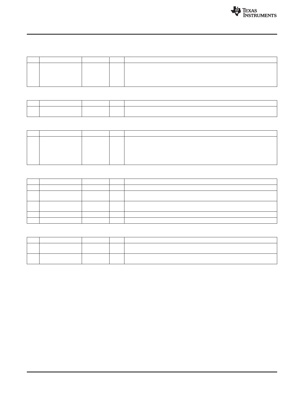
3.6 Registers
DBGDATA (0x6260) – Debug Data
Bit Name Reset R/W Description
7:0
BYTE[7:0]
0 R Debug data from BURST_WRITE command
This register is updated each time a new byte has been transferred to the debug
interface using the BURST_WRITE command. A DBG_BW DMA trigger is
generated when this byte is updated. This allows the DMA controller to fetch the
data.
CHVER (0x6249) – Chip Version
Bit Name Reset R/W Description
7:0
VERSION[7:0]
Chip R Chip revision number
dependent
CHIPID (0x624A) – Chip ID
Bit Name Reset R/W Description
7:0
CHIPID[7:0]
Chip R Chip identification number.
dependent CC2530: 0xA5
CC2531: 0xB5
CC2533: 0x95
CC2540: 0x8D
CC2541: 0x41
CHIPINFO0 (0x6276) – Chip Information Byte 0
Bit Name Reset R/W Description
7 – 0 R0 Reserved. Always 0.
6:4
FLASHSIZE[2:0]
Chip R Flash Size. 001 – 32 KB, 010 – 64 KB, 011 – 128 KB (for CC2533: 011 – 96 KB),
dependent 100 – 256 KB
3
USB
Chip R 1 if chip has USB, 0 otherwise
dependent
2 – 1 R1 Reserved. Always 1
1:0 – 00 R0 Reserved. Always 00
CHIPINFO1 (0x6277) – Chip Information Byte 1
Bit Name Reset R/W Description
7:3 – Chip R Reserved.
dependent
2:0
SRAMSIZE[2:0]
Chip R SRAM size in KB minus 1. For example, a 4-KB device has this field set to 011. Add
dependent 1 to the number to get the number of KB available.
62
Debug Interface SWRU191C–April 2009–Revised January 2012
Submit Documentation Feedback
Copyright © 2009–2012, Texas Instruments Incorporated