www.ti.com
ADC Operation
12.2.10 ADC Registers
This section describes the ADC registers.
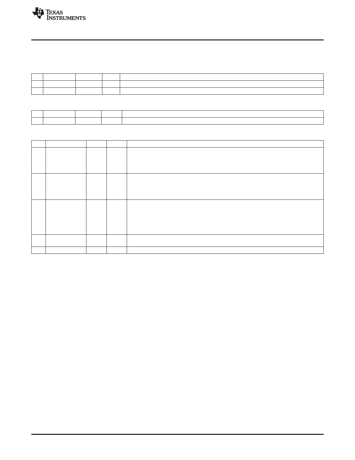
ADCL (0xBA) – ADC Data, Low
Bit Name Reset R/W Description
7:2
ADC[5:0]
0000 00 R Least-significant part of ADC conversion result
1:0 – 00 R0 Reserved. Always read as 0
ADCH (0xBB) – ADC Data, High
Bit Name Reset R/W Description
7:0
ADC[13:6]
0x00 R Most-significant part of ADC conversion result
ADCCON1 (0xB4) – ADC Control 1
Bit Name Reset R/W Description
7
EOC
0 R/H0 End of conversion. Cleared when ADCH has been read. If a new conversion is completed
before the previous data has been read, the EOC bit remains high.
0: Conversion not complete
1: Conversion completed
6
ST
0 R/W1/ Start conversion. Read as 1 until conversion has completed
H0
0: No conversion in progress
1: Start a conversion sequence if ADCCON1.STSEL = 11 and no sequence is running.
5:4
STSEL[1:0]
11 R/W Start select. Selects the event that starts a new conversion sequence
00: External trigger on P2.0 pin
01: Full speed. Do not wait for triggers
10: Timer 1 channel 0 compare event
11: ADCCON1.ST = 1
3:2 – 00 R/W Controls the 16-bit random-number generator. See ADCCON1 (0xB4) – ADC Control 1
description in Section 14.3.
1:0 – 11 R/W Reserved. Always set to 11
141
SWRU191C–April 2009–Revised January 2012 ADC
Submit Documentation Feedback
Copyright © 2009–2012, Texas Instruments Incorporated