Time
Byte/Word n – 1
Byte/Word n
Byte/Word 1
Byte/Word 2
Byte/Word 3
•
•
•
LENGTH = n
Byte/Word n – 1 Byte/Word n – 1 Byte/Word n – 1
Byte/Word n Byte/Word n
Byte/Word n + 1 Byte/Word n + 1
Byte/Word n + 2
Byte/Word 1 Byte/Word 1 Byte/Word 1
Byte/Word 2 Byte/Word 2 Byte/Word 2
Byte/Word 3 Byte/Word 3 Byte/Word 3
•
•
•
•
•
•
•
•
•
LENGTH = n LENGTH = n LENGTH = n
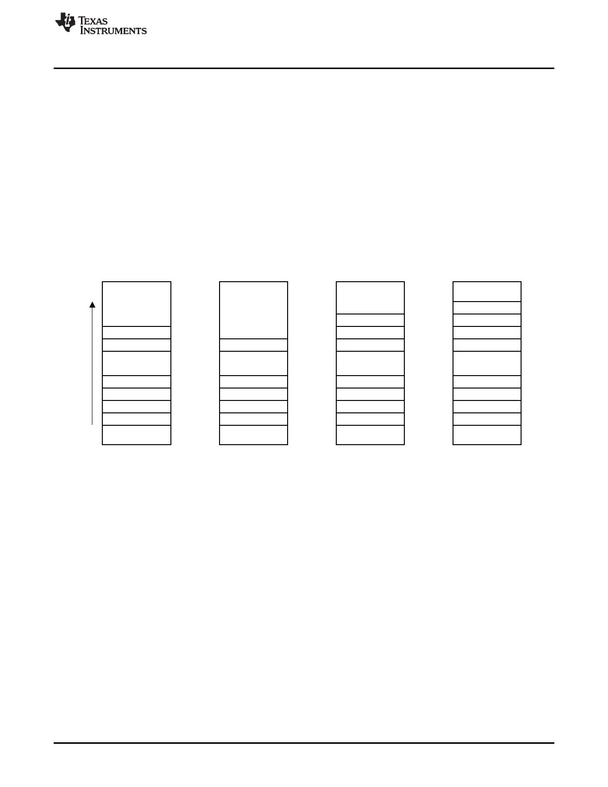
VLEN = 001 VLEN = 010 VLEN = 011 VLEN = 100
M0103-02
www.ti.com
DMA Configuration Parameters
the transfer length. This allows variable-length transfers. When using variable-length transfer, various
options regarding how to count number of bytes to transfer is given. In any case, the transfer-count (LEN)
setting is used as a maximum transfer count. If the transfer length specified by the first byte or word is
greater than LEN, then LEN bytes/words are transferred. When using variable-length transfers, then LEN
should be set to the largest allowed transfer length plus one.
Note that the M8 bit (Section 8.2.11) is only used when byte-size transfers are chosen.
Options which can be set with VLEN are the following:
1. Transfer number of bytes/words commanded by first byte/word + 1 (transfers the length byte/word, and
then as many bytes/words as dictated by the length byte/word)
2. Transfer number of bytes/words commanded by first byte/word
3. Transfer number of bytes/words commanded by first byte/word + 2 (transfers the length byte/word, and
then as many bytes/words as dictated by the length byte/word + 1)
4. Transfer number of bytes/words commanded by first byte/word + 3 (transfers the length byte/word, and
then as many bytes/words as dictated by the length byte/word + 2)
Figure 8-2 shows the VLEN options.
Figure 8-2. Variable Length (VLEN) Transfer Options
8.2.5 Trigger Event
Each DMA channel can be set up to sense on a single trigger. This field determines which trigger the
DMA channel senses.
8.2.6 Source and Destination Increment
When the DMA channel is armed or rearmed, the source and destination addresses are transferred to
internal address pointers. The possibilities for address increment are:
• Increment by zero. The address pointer remains fixed after each transfer.
• Increment by one. The address pointer increments one count after each transfer.
• Increment by two. The address pointer increments two counts after each transfer.
• Decrement by one. The address pointer decrements one count after each transfer.
where a count equals 1 byte in byte mode and 2 bytes in word mode.
8.2.7 DMA Transfer Mode
The transfer mode determines how the DMA channel behaves when it starts transferring data. There are
four transfer modes described as follows:
99
SWRU191C–April 2009–Revised January 2012 DMA Controller
Submit Documentation Feedback
Copyright © 2009–2012, Texas Instruments Incorporated