c
f 2405 5(k 11) MHz k 11, 26= + - Î
é ù é ù
ë û ë û
Frequency and Channel Programming
www.ti.com
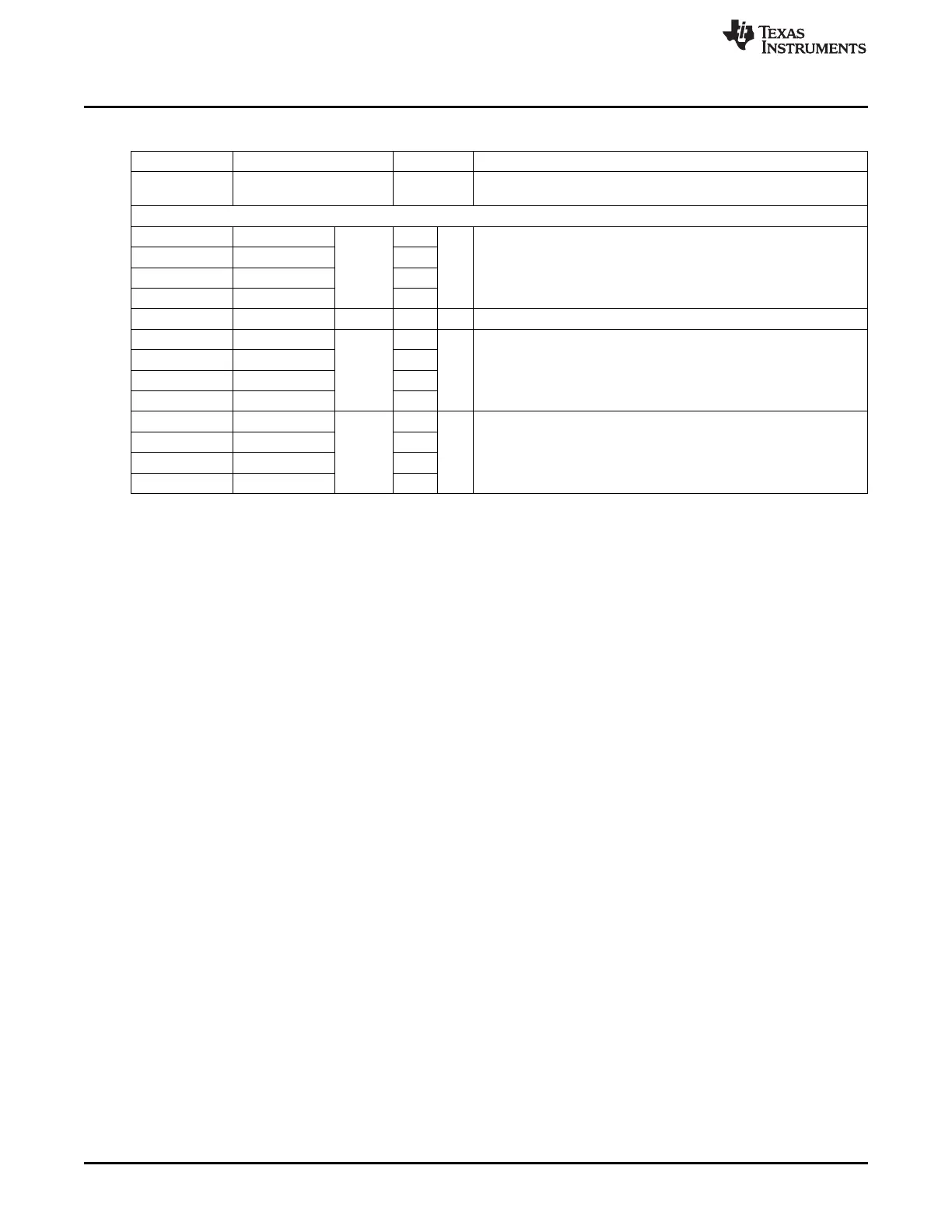
Table 23-1. Frame Filtering and Source Matching Memory Map (continued)
ADDRESS REGISTER/VARIABLE ENDIAN DESCRIPTION
Extended address matching. When there is a match on entry ext_n,
0x6160 SRCRESMASK0
bits 2n and 2n + 1 are set in SRCRESMASK.
SOURCE ADDRESS TABLE
0x615E–0x615F short_23 LE
0x615C–0x615D panid_23 LE
Two individual short-address entries (combination of 16-bit PAN ID
ext_11 LE
and 16-bit short address) or one extended address entry
0x615A–0x615B short_22 LE
0x6158–0x6159 panid_22 LE
... ... ... ... ... ...
0x610E–0x610F short_03 LE
0x610C–0x610D panid_03 LE
Two individual short address entries (combination of 16-bit PAN ID
ext_01 LE
and 16-bit short address) or one extended address entry
0x610A–0x610B short_02 LE
0x6108–0x6109 panid_02 LE
0x6106–0x6107 short_01 LE
0x6104–0x6105 panid_01 LE
Two individual short address entries (combination of 16-bit PAN ID
ext_00 LE
and 16-bit short address) or one extended address entry
0x6102–0x6103 short_00 LE
0x6100–0x6101 panid_00 LE
23.5 Frequency and Channel Programming
The carrier frequency is set by programming the 7-bit frequency word located in FREQCTRL.FREQ[6:0].
Changes take effect after the next recalibration. Carrier frequencies in the range from 2394 MHz to 2507
MHz are supported. The carrier frequency f
C
, in MHz, is given by f
C
= (2394 + FREQCTRL.FREQ[6:0])
MHz, and is programmable in 1-MHz steps.
IEEE 802.15.4-2006 specifies 16 channels within the 2.4-GHz band. They are numbered 11 through 26
and are 5 MHz apart. The RF frequency of channel k is given by Equation 4.
(4)
For operation in channel k, the FREQCTRL.FREQ register should therefore be set to
FREQCTRL.FREQ = 11 + 5 (k – 11).
23.6 IEEE 802.15.4-2006 Modulation Format
This section is meant as an introduction to the 2.4-GHz direct-sequence spread-spectrum (DSSS) RF
modulation format defined in IEEE 802.15.4-2006. For a complete description, see the standard document
[1].
The modulation and spreading functions are illustrated at the block level in Figure 23-1. Each byte is
divided into two symbols, 4 bits each. The least-significant symbol is transmitted first. For multibyte fields,
the least-significant byte is transmitted first, except for security-related fields, where the most-significant
byte is transmitted first.
Each symbol is mapped to one out of 16 pseudorandom sequences, 32 chips each. The symbol-to-chip
mapping is shown in Table 23-2. The chip sequence is then transmitted at 2 Mchips/s, with the
least-significant chip (C
0
) transmitted first for each symbol. The transmitted bit stream and the chip
sequences are observable on GPIO pins P1[0:5]. See Chapter 7 for details on how to configure the GPIO
to do this.
226
CC253x Radio SWRU191C–April 2009–Revised January 2012
Submit Documentation Feedback
Copyright © 2009–2012, Texas Instruments Incorporated