www.ti.com
USART Registers
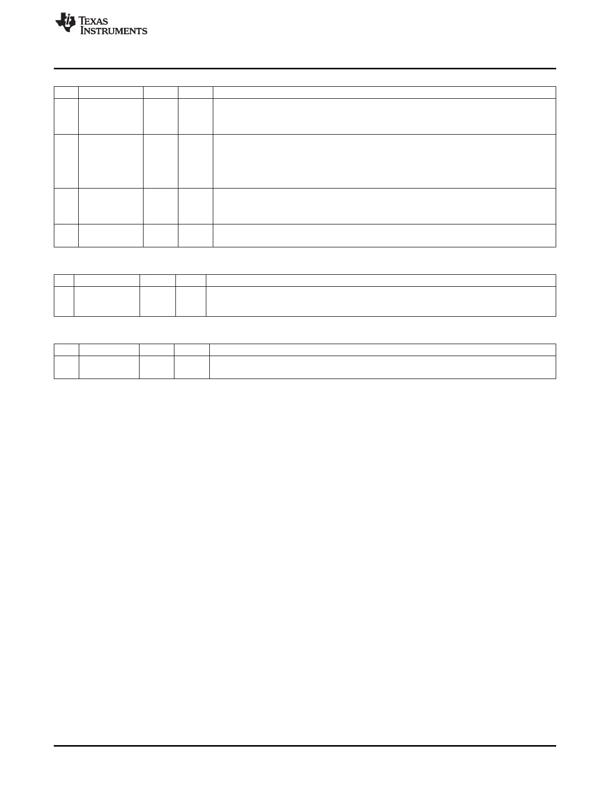
U1GCR (0xFC) – USART 1 Generic Control
Bit Name Reset R/W Description
7
CPOL
0 R/W SPI clock polarity
0: Negative clock polarity
1: Positive clock polarity
6
CPHA
0 R/W SPI clock phase
0: Data is output on MOSI when SCK goes from CPOL inverted to CPOL, and data input
is sampled on MISO when SCK goes from CPOL to CPOL inverted.
1: Data is output on MOSI when SCK goes from CPOL to CPOL inverted, and data input
is sampled on MISO when SCK goes from CPOL inverted to CPOL.
5
ORDER
0 R/W Bit order for transfers
0: LSB first
1: MSB first
4:0
BAUD_E[4:0]
0 0000 R/W
Baud rate exponent value. BAUD_E along with BAUD_M determines the UART baud rate
and the SPI master SCK clock frequency.
U1DBUF (0xF9) – USART 1 Receive/Transmit Data Buffer
Bit Name Reset R/W Description
7:0
DATA[7:0]
0x00 R/W USART receive and transmit data. When writing this register, the data written is written to the
internal transmit-data register. When reading this register, the data from the internal read-data
register is read.
U1BAUD (0xFA) – USART 1 Baud-Rate Control
Bit Name Reset R/W Description
7:0
BAUD_M[7:0]
0x00 R/W
Baud rate mantissa value. BAUD_E along with BAUD_M determines the UART baud rate and
the SPI master SCK clock frequency.
171
SWRU191C–April 2009–Revised January 2012 USART
Submit Documentation Feedback
Copyright © 2009–2012, Texas Instruments Incorporated