FIFO Access
www.ti.com
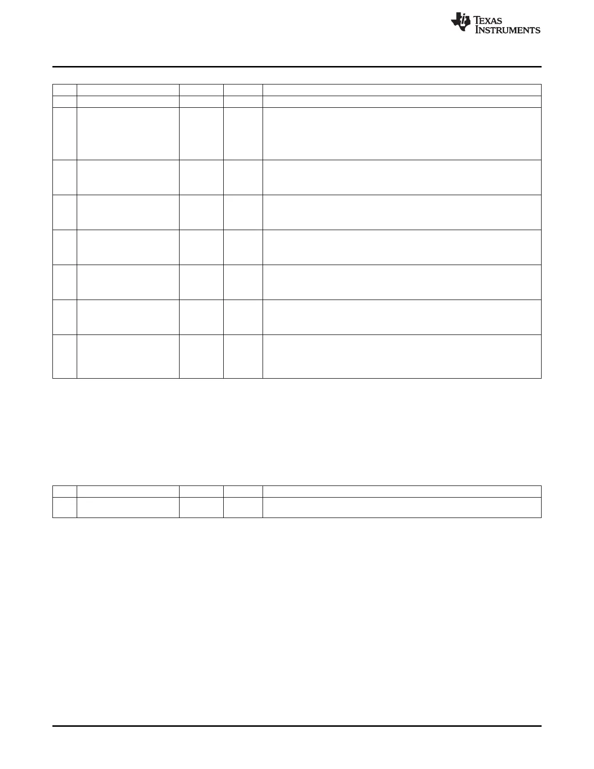
RFERRM (0x61A5) – RF Error Interrupt Masks
Bit Name Reset R/W Description
7 – 0 R0 Reserved. Read as 0
7:6
STROBEERR
0 R/W A command strobe was issued at a time it could not be processed. Triggered if
trying to disable radio when already disabled, or when trying to do a SACK,
SACKPEND, or SNACK command when not in active RX.
0: Interrupt disabled
1: Interrupt enabled
5
TXUNDERF
0 R/W TXFIFO underflowed
0: Interrupt disabled
1: Interrupt enabled
4
TXOVERF
0 R/W TXFIFO overflowed
0: Interrupt disabled
1: Interrupt enabled
3
RXUNDERF
0 R/W RXFIFO underflowed
0: Interrupt disabled
1: Interrupt enabled
2
RXOVERF
0 R/W RXFIFO overflowed
0: Interrupt disabled
1: Interrupt enabled
1
RXABO
0 R/W Reception of a frame was aborted.
0: Interrupt disabled
1: Interrupt enabled
0
NLOCK
0 R/W Frequency synthesizer failed to achieve lock after timeout, or lock is lost during
reception. Receiver must be restarted to clear this error situation.
0: Interrupt disabled
1: Interrupt enabled
23.2 FIFO Access
The TXFIFO and RXFIFO may be accessed though the SFR register RFD (0xD9). Data is written to the
TXFIFO when writing to the RFD register. Data is read from the RXFIFO when the RFD register is read.
The XREG registers RXFIFOCNT and TXFIFOCNT provide information on the amount of data in the
FIFOs. The FIFO contents can be cleared by issuing SFLUSHRX and SFLUSHTX.
RFD (0xD9) – RF Data
Bit Name Reset R/W Description
7:0
RFD[7:0]
0x00 R/W Data written to the register is written to the TXFIFO. When reading this
register, data from the RXFIFO is read.
23.3 DMA
It is possible to use direct memory access (DMA) to move data between memory and the radio. The DMA
controller is described in Chapter 8. See this section for a detailed description on how to set up and use
DMA transfers.
To support the DMA controller, there is one DMA trigger associated with the radio, the RADIO DMA trigger
(DMA trigger 19). The RADIO DMA trigger is activated by two events. The first event to cause a RADIO
DMA trigger is when the first data is present in the RXFIFO, i.e. when the RXFIFO goes from the empty
state to a nonempty state. The second event that causes a RADIO DMA trigger is when data is read from
the RXFIFO (through RFD) and there is still more data available in the RXFIFO.
23.4 Memory Map
The RF Core contains 384 bytes of physical RAM located at addresses 0x6000 to 0x0617F. The
configuration and status registers of the RF Core are located at addresses from 0x6180 to 0x61EF.
Configuration registers, RXFIFO, and TXFIFO are all preserved during sleep modes.
224
CC253x Radio SWRU191C–April 2009–Revised January 2012
Submit Documentation Feedback
Copyright © 2009–2012, Texas Instruments Incorporated