www.ti.com
Interrupts
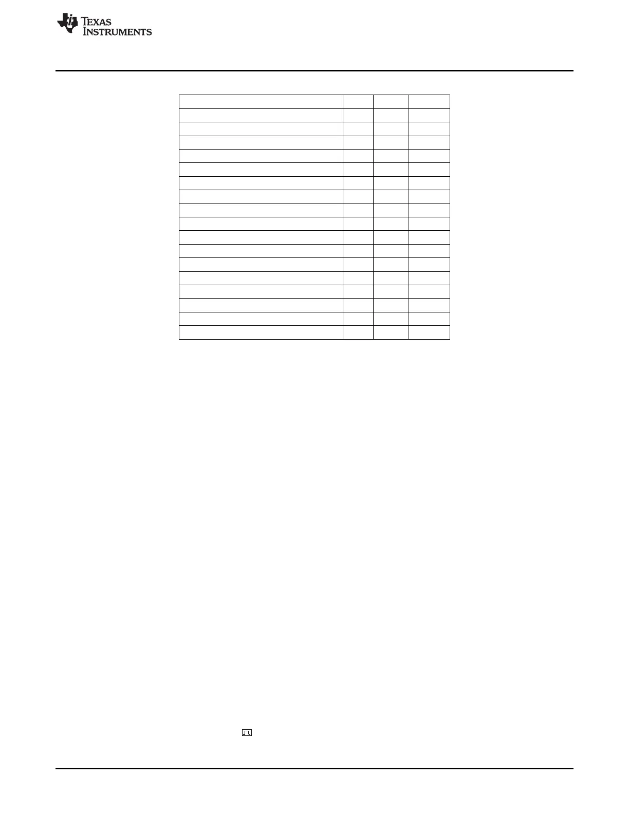
Table 2-4. Instructions That Affect Flag Settings
(1)
Instruction CY OV AC
ADD x x x
ADDC x x x
SUBB x x x
MUL 0 x –
DIV 0 x –
DA x – –
RRC x – –
RLC x – –
SETB C 1 – –
CLR C x – –
CPLC x – –
ANL C,bit x – –
ANL C,/bit x – –
ORL C,bit x – –
ORL C,/bit x – –
MOV C,bit x – –
CJNE x – –
(1)
0 = set to 0, 1 = set to 1, x = set to 0/1, – = not affected
2.5 Interrupts
The CPU has 18 interrupt sources. Each source has its own request flag located in a set of interrupt flag
SFR registers. Each interrupt requested by the corresponding flag can be individually enabled or disabled.
The definitions of the interrupt sources and the interrupt vectors are given in Table 2-5.
The interrupts are grouped into a set of priority-level groups with selectable priority levels.
The interrupt-enable registers are described in Section 2.5.1 and the interrupt priority settings are
described in Section 2.5.3.
2.5.1 Interrupt Masking
Each interrupt can be individually enabled or disabled by the interrupt-enable bits in the interrupt-enable
SFRs IEN0, IEN1, and IEN2. The CPU interrupt-enable SFRs are described as follows and summarized
in Table 2-5.
Note that some peripherals have several events that can generate the interrupt request associated with
that peripheral. This applies to Port 0, Port 1, Port 2, Timer 1, Timer 2, Timer 3, Timer 4, DMA controller,
and Radio. These peripherals have interrupt mask bits for each internal interrupt source in the
corresponding SFR or XREG registers.
In order to enable any of the interrupts, the following steps must be taken:
1. Clear interrupt flags.
2. Set individual interrupt-enable bit in the peripherals SFR register, if any.
3. Set the corresponding individual interrupt-enable bit in the IEN0, IEN1, or IEN2 register to 1.
4. Enable global interrupt by setting the EA bit in IEN0 to 1.
5. Begin the interrupt service routine at the corresponding vector address of that interrupt. See Table 2-5
for addresses.
Figure 2-4 gives a complete overview of all interrupt sources and associated control and state registers.
Shaded boxes in Figure 2-4 are interrupt flags that are automatically cleared by hardware when the
interrupt service routine is called. indicates a one-shot, either due to the level source or due to edge
shaping. Interrupts missing this are to be treated as level-triggered (apply to ports P0, P1, and P2). The
43
SWRU191C–April 2009–Revised January 2012 8051 CPU
Submit Documentation Feedback
Copyright © 2009–2012, Texas Instruments Incorporated