Interrupts
www.ti.com
switch boxes are shown in the default state, and or indicates rising- or falling-edge detection, i.e., at
what time instance the interrupt is generated. As a general rule for pulsed or edge-shaped interrupt
sources, one should clear CPU interrupt flag registers prior to clearing the source flag bit, if available, for
flags that are not automatically cleared. For level sources, one must clear the source prior to clearing the
CPU flag.
Note that when clearing source interrupt flags in a register that contains several flags, interrupts may be
lost if a read-modify-write operation is done (even in a single assembly instruction), as it will also clear
interrupt flags that became active between the read and write operation. The source interrupt flags (with
the exception of the USB controller interrupt flags) have the access mode R/W0. This means that writing 1
to a bit has no effect, so 1 should be written to an interrupt flag that is not to be cleared. For instance, to
clear the TIMER2_OVF_PERF bit (bit 3) of T2IRQF in C code, one should do:
T2IRQF = ~(1 << 3);
and not:
T2IRQF &= ~(1 << 3); //
wrong!
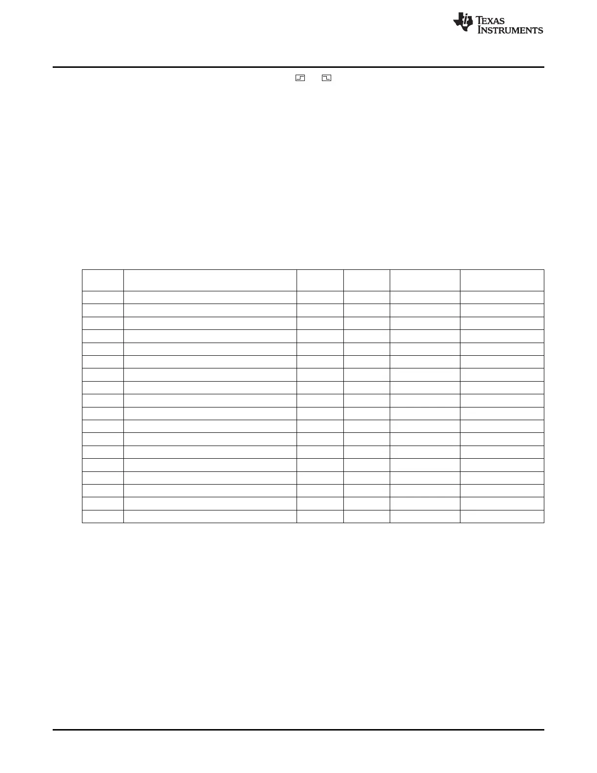
Table 2-5. Interrupts Overview
Interrupt Interrupt Interrupt Interrupt Mask,
Description Interrupt Flag, CPU
Number Name Vector CPU
0 RF core error situation RFERR 0x03
IEN0.RFERRIE TCON.RFERRIF
(1)
1 ADC end of conversion ADC 0x0B
IEN0.ADCIE TCON.ADCIF
(1)
2 USART 0 RX complete URX0 0x13
IEN0.URX0IE TCON.URX0IF
(1)
3 USART 1 RX complete URX1 0x1B
IEN0.URX1IE TCON.URX1IF
(1)
4 AES encryption/decryption complete ENC 0x23
IEN0.ENCIE S0CON.ENCIF
5 Sleep Timer compare ST 0x2B
IEN0.STIE IRCON.STIF
6 Port-2 inputs/USB/I
2
C P2INT 0x33
IEN2.P2IE IRCON2.P2IF
(2)
7 USART 0 TX complete UTX0 0x3B
IEN2.UTX0IE IRCON2.UTX0IF
8 DMA transfer complete DMA 0x43
IEN1.DMAIE IRCON.DMAIF
9 Timer 1 (16-bit) capture/compare/overflow T1 0x4B
IEN1.T1IE IRCON.T1IF
(1) (2)
10 Timer 2 T2 0x53
IEN1.T2IE IRCON.T2IF
(1) (2)
11 Timer 3 (8-bit) capture/compare/overflow T3 0x5B
IEN1.T3IE IRCON.T3IF
(1) (2)
12 Timer 4 (8-bit) capture/compare/overflow T4 0x63
IEN1.T4IE IRCON.T4IF
(1) (2)
13 Port 0 inputs P0INT 0x6B
IEN1.P0IE IRCON.P0IF
(2)
14 USART 1 TX complete UTX1 0x73
IEN2.UTX1IE IRCON2.UTX1IF
15 Port 1 inputs P1INT 0x7B
IEN2.P1IE IRCON2.P1IF
(2)
16 RF general interrupts RF 0x83
IEN2.RFIE S1CON.RFIF
(2)
17 Watchdog overflow in timer mode WDT 0x8B
IEN2.WDTIE IRCON2.WDTIF
(1)
Hardware-cleared when interrupt service routine is called
(2)
Additional IRQ mask and IRQ flag bits exist.
44
8051 CPU SWRU191C–April 2009–Revised January 2012
Submit Documentation Feedback
Copyright © 2009–2012, Texas Instruments Incorporated