USB PHY
DP
DM
EP0
EP1
EP2
EP3
EP4
EP5
USB Controller
USB SIE
1KB
SRAM
(FIFOs)
Memory
Arbiter
B0305-01
USB Introduction
www.ti.com
21.1 USB Introduction
The USB controller monitors the USB for relevant activity and handles packet transfers.
Appropriate response to USB interrupts and loading/unloading of packets into/from endpoint FIFOs is the
responsibility of the firmware. The firmware must be able to reply correctly to all standard requests from
the USB host and work according to the protocol implemented in the driver on the PC.
The USB controller has the following features:
• Full-speed operation (up to 12 Mbps)
• Five endpoints (in addition to endpoint 0) that can be used as IN, OUT, or IN/OUT and can be
configured as bulk/interrupt or isochronous.
• 1-KB SRAM FIFO available for storing USB packets
• Endpoints supporting packet sizes from 8–512 bytes
• Support for double buffering of USB packets
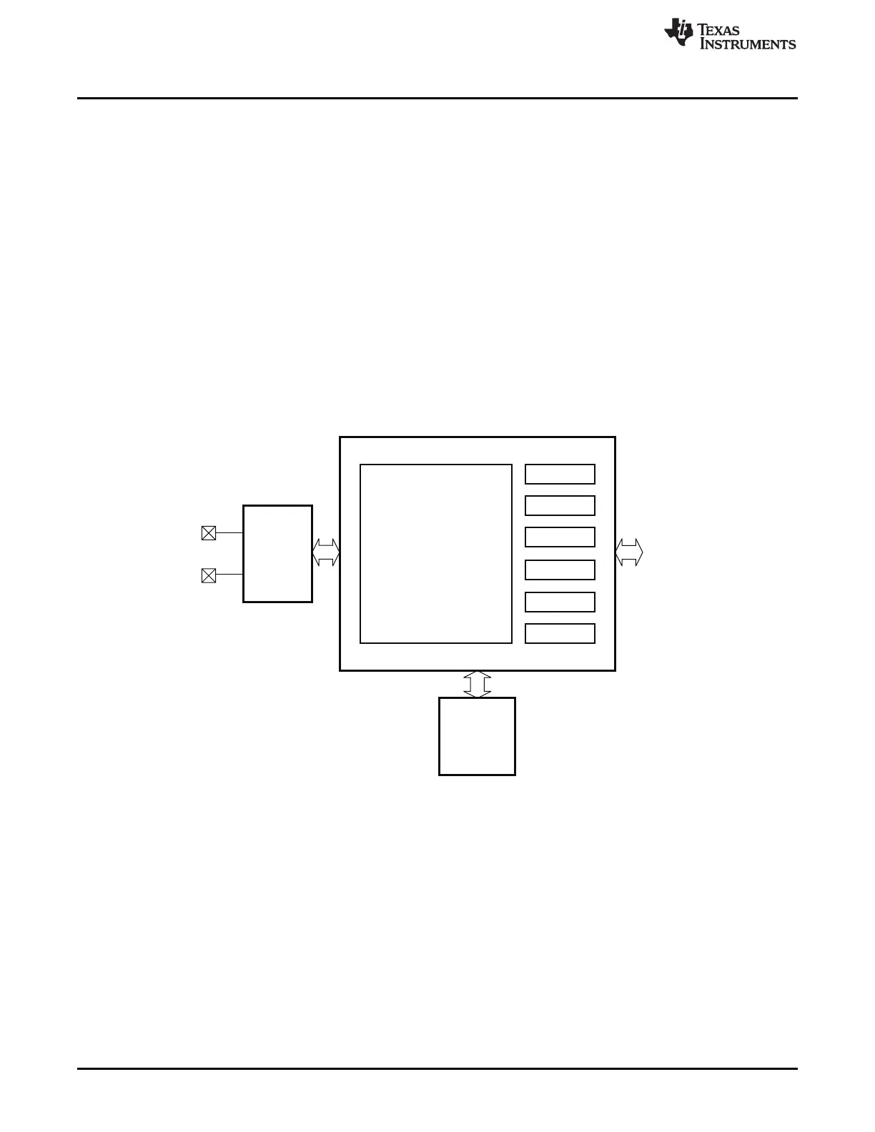
Figure 21-1 shows a block diagram of the USB controller. The USB PHY is the physical interface with
input and output drivers. The USB SIE is the serial-interface engine, which controls the packet transfer
to/from the endpoints. The USB controller is connected to the rest of the system through the memory
arbiter.
Figure 21-1. USB Controller Block Diagram
21.2 USB Enable
The USB is enabled by setting USBCTRL.USB_EN to 1. Setting USBCTRL.USB_EN to 0 resets the USB
controller.
21.3 48-MHz USB PLL
The 48-MHz internal USB PLL must be powered up and stable for the USB controller to operate correctly.
It is important that the crystal oscillator is selected as souce and is stable before the USB PLL is enabled.
The USB PLL is enabled by setting the USBCTRL.PLL_EN bit and waiting for the USBCTRL.PLL_LOCKED
status flag to go high. When the PLL has locked, it is safe to use the USB controller.
Note: The PLL must be disabled before exiting active mode and re-enabled after entering active mode.
192
USB Controller SWRU191C– April 2009– Revised January 2012
Submit Documentation Feedback
Copyright © 2009–2012, Texas Instruments Incorporated