194
Explanation
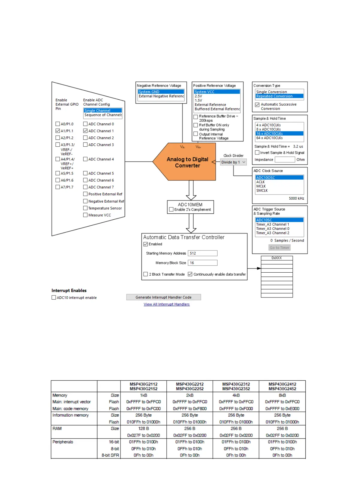
Use Power User setup screen of Grace to configure the DTC. Observe the setup as shown below:
Here only channel 1 was used. The setup is similar to the first ADC10 example setup. The main
difference is the enabling of the DTC block. Note the starting memory address and the memory block
size. The memory we are talking about here is no other than MSP430’s RAM. Unless you want to assign
a different pointer address, keep it untouched. So why is it pointed at RAM location 512 (0x200) by
default? The answer is the fact that this is first RAM location for our target MSP430G2452
microcontroller. Check the memory map below: