281
USI I2C – Interfacing PCF8574 I/O Expander
I2C is another popular form of on board synchronous serial communication developed by NXP. It just
uses two wires for communication and so it is also referred as Two Wire Interface (TWI). Just like SPI,
I2C is widely used in interfacing real-time clocks (RTC), digital sensors, memory chips and so on. It
rivals SPI but compared to SPI it is slower and have some limitations. Typical bus speed ranges from a
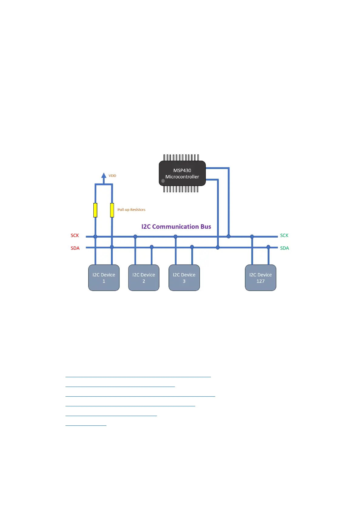
few kilohertz to 400kHz. Up to 127 devices can coexist in an I2C bus. In an I2C bus it is not possible, by
conventional means to interface devices with same device IDs or devices with different logic voltage
levels without logic level converters and so on. Still however, I2C is very popular because these issues
rarely arise and because of its simplicity. Unlike other communications, there’s no pin/wire swapping
as two wires connect straight to the bus – SDA to SDA and SCL to SCL.
As with SPI, an I2C bus must contain one master and one or more slaves. The master is solely
responsible for generating clock signals and initiating communication. Communication starts when
master sends out a slave’s ID with read/write command and request. The slave reacts to this command
by processing the request from the master and sending out data or processing it. I2C bus is always
pulled-up using pull-up resistors. Without these pull-up resistors, I2C bus may not function properly.
To know more about I2C interface visit the following links:
• https://learn.mikroe.com/i2c-everything-need-know/
• https://learn.sparkfun.com/tutorials/i2c
• http://www.ti.com/lsds/ti/interface/i2c-overview.page
• http://www.robot-electronics.co.uk/i2c-tutorial
• https://www.i2c-bus.org/i2c-bus/
• http://i2c.info/
Other protocols like SMBus and I2S have similarities with I2C and so learning about I2C advances
learning these too.