41
// Clear OSC fault flag
IFG1 &= ~OFIFG;
// 50us delay
__delay_cycles(25);
} while (IFG1 & OFIFG);
/*
* SR, Status Register
*
* ~SCG1 -- Disable System clock generator 1
* ~SCG0 -- Disable System clock generator 0
* ~OSCOFF -- Oscillator On
* ~CPUOFF -- CPU On
* GIE -- General interrupt enable
*
* Note: ~<BIT> indicates that <BIT> has value zero
*/
__bis_SR_register(GIE);
/* USER CODE START (section: System_graceInit_epilogue) */
/* User code */
/* USER CODE END (section: System_graceInit_epilogue) */
}
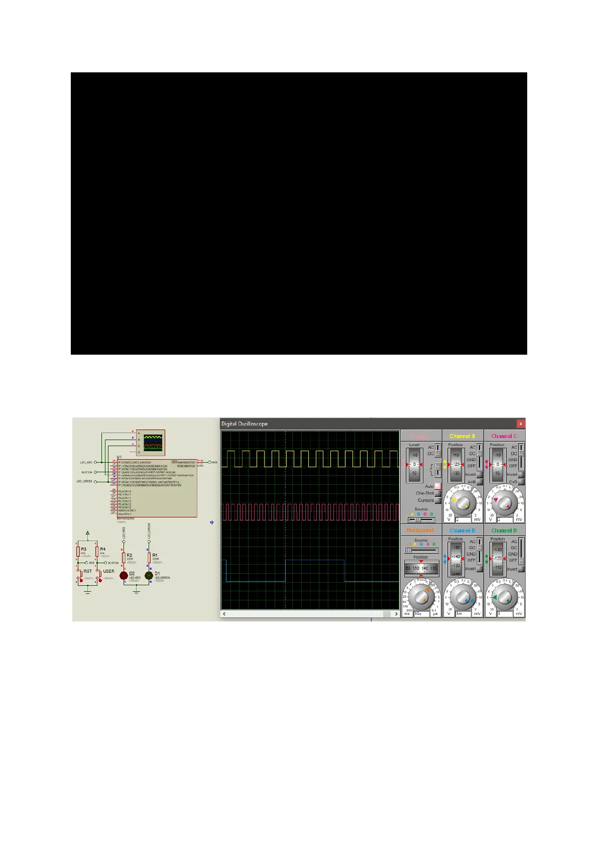
Simulation
Explanation
The demo example here is primarily used to extract SMCLK and ACLK signals. Here we just verified if
these signals are as they are supposed to be. Using GRACE, we set MCLK 500 kHz, SMCLK 1500 Hz and
ACLK 12 kHz. Clock outputs are obtained from respective pins as shown in the snap. The only thing
additional here (not shown) is the P1.6 digital I/O. In the code, this I/O is toggled every one CPU cycle.
It is not an indicator of CPU clock speed but just a test of I/O toggling speed for. MCLK has no output
associated with it and so we can’t see its signal.